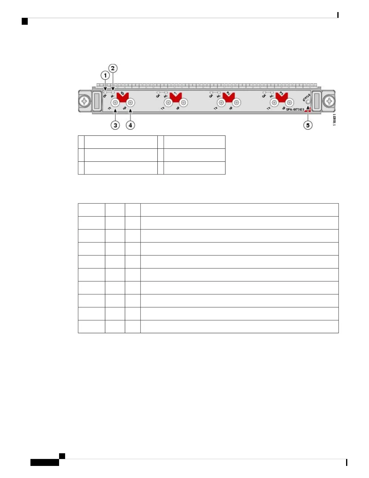
Figure 21: 2-Port and 4-Port Clear Channel T3/E3 SPA Faceplate
RX (Receive) connector4C/A (Carrier/Alarm) LED1
STATUS LED5A/L (Active Loopback) LED2
TX (Transmit) connector3
The following table describes the 2-Port and 4-Port Clear Channel T3/E3 SPA LEDs.
Table 19: 2-Port and 4-Port Clear Channel T3/E3 SPA LEDs
MeaningStateColorLED Label
Port is not enabled by software.OffOffC/A
Port is enabled by software, and there is a valid E3 or T3 signal without any alarms.OnGreen
Port is enabled by software, and there is at least one alarm.OnAmber
Port is not enabled by software.OffOffA/L
Port is enabled by software, and loopback is off.OnGreen
Port is enabled by software, and loopback is on.OnAmber
SPA power is off.OffOffSTATUS
SPA is ready and operational.OnGreen
SPA power is on and good, and the SPA is being configured.OnAmber
2-Port and 4-Port Clear Channel T3/E3 SPA Interface Specifications
The framer processes incoming and outgoing T3 (cbit, m13/m23, and unframe) and E3 (g751, g832, and
unframe) frames. The framer operates at T3/E3 line rates (44.736 /34.368 Mbps) depending on the mode in
which it is configured.
Packet data is transported with a user-configurable encapsulation (such as Point-to-Point Protocol [PPP] or
High-Level Data Link Control [HDLC]), and is mapped to T3 and E3 frames. The encapsulations add transport
overhead to the packet of data frames before transporting, and are stripped when a packet is transported to
the far end.
Cisco ASR 9000 Series Aggregation Services Router SIP and SPA Hardware Installation Guide
30
Overview: Cisco ASR 9000 Series Router Shared Port Adapters
2-Port and 4-Port Clear Channel T3/E3 SPA Interface Specifications

 Loading...


