8-Port Channelized T1/E1 SPA Cables, Connectors, and Pinouts
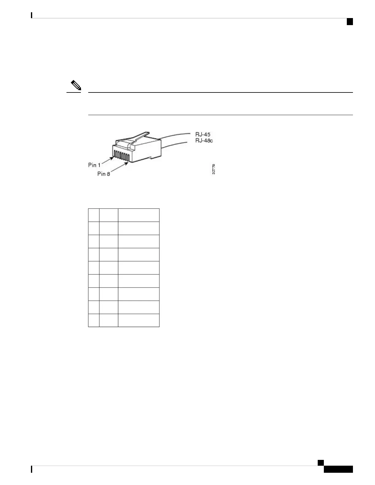
The following figure shows an RJ-45 connector.
The terms RJ-45 and RJ-48c are sometimes used interchangeably. The RJ-48c is the jack or receptacle; the
RJ-45 is the connector.
Note
Figure 24: RJ-45 Connector
The following table describes the signals and connector pinouts for RJ-45 cable connectors.
Table 24: RJ-45 Connector Pinouts
DescriptionSignalPin
Receive ring –RX–1
Receive tip +RX+2
No connectionNC3
Transmit ring –TX–4
Transmit tip +TX+5
No connectionNC6
No connectionNC7
No connectionNC8
1-Port Channelized STM-1/OC-3 SPA Overview
The following sections describe the 1-Port Channelized STM-1/OC-3 SPA:
1-Port Channelized STM-1/OC-3 SPA LEDs
The 1-Port Channelized STM-1/OC-3 SPA has two types of LEDs: an A/L LED for the port and a STATUS
LED, as shown in the following figure.
Cisco ASR 9000 Series Aggregation Services Router SIP and SPA Hardware Installation Guide
35
Overview: Cisco ASR 9000 Series Router Shared Port Adapters
8-Port Channelized T1/E1 SPA Cables, Connectors, and Pinouts

 Loading...


