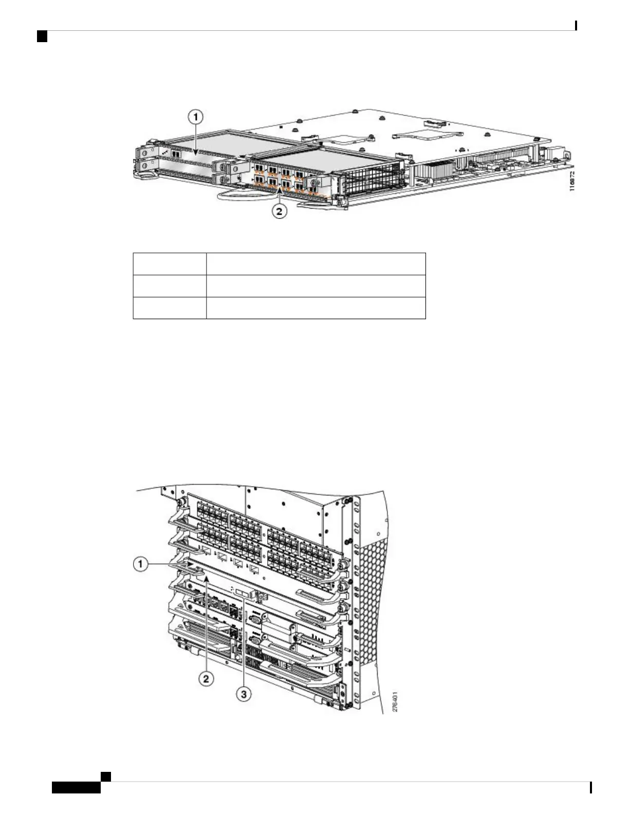
Figure 3: Subslot Locations for the 2-Port Channelized OC-12/DS0 SPA
Table 7: Subslot Locations for the 2-Port Channelized OC-12/DS0 SPA
DescriptionCall Out Number
Single height single width SPA in Subslot 1, Bay 01
Double height single width SPA in Subslot 0, Bay 32
SPA Interface Addresses on the Cisco ASR 9000 SIP-700
A Cisco ASR 9000 Series Aggregation Services Router identifies a SPA interface address by its rack number,
SIP slot number, SPA subslot, and port number on the SPA, in the format rack/slot/subslot/port . Subslots
and ports are numbered starting from 0, so each Cisco ASR 9000 SIP-700 has two subslots 0 (left) and 1
(right). For example, the interface addresses of a 2-port SPA located in the second SIP subslot, where the SIP
is inserted into router line card slot 3 in rack 0 are 0/3/1/0 and 0/3/1/1. The following figure shows the slot,
subslot, and port locations for the 2-Port Channelized OC-12/DS0 SPA on a Cisco ASR 9006 6-slot chassis.
Figure 4: Slot, Subslot, and Port Locations for the 2-Port Channelized OC-12/DS0 SPA on a Cisco ASR 9006 Chassis
Cisco ASR 9000 Series Aggregation Services Router SIP and SPA Hardware Installation Guide
6
Overview: Cisco ASR 9000 Series Router SPA Interface Processors
SPA Interface Addresses on the Cisco ASR 9000 SIP-700

 Loading...


