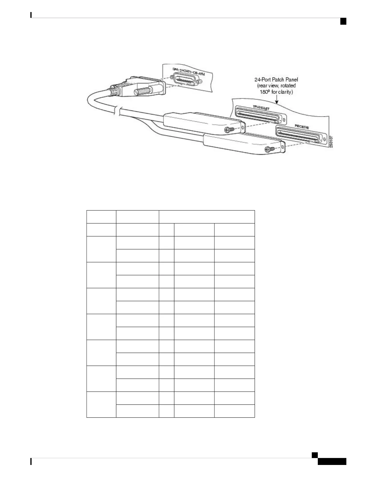
Figure 53: Cable Installation Between the SPA and the Patch Panel
SPA Cable Pinouts
The following table shows the cable pinouts for the cable (part number CABLE-24T1E1J1) that is installed
between the 24-Port Channelized T1/E1/J1 CEoP SPA and the rear of the patch panel.
Table 40: 24-Port Channelized T1/E1/J1 CEoP SPA Cable Connector Pinouts
Connector PinsSubscriber
RX Cable LeadTX Cable LeadSPASignalLine
Not connected126252TX TipTX RingLine 1
126Not connected2676RX TipRX Ring
Not connected
227353TX TipTX RingLine 2
227Not connected2777RX TipRX Ring
Not connected
328454TX TipTX RingLine 3
328Not connected2878RX TipRX Ring
Not connected
429555TX TipTX RingLine 4
429Not connected2979RX TipRX Ring
Not connected
530656TX TipTX RingLine 5
530Not connected3080RX TipRX Ring
Not connected
631757TX TipTX RingLine 6
631Not connected3181RX TipRX Ring
Not connected
732858TX TipTX RingLine 7
732Not connected3282RX TipRX Ring
Cisco ASR 9000 Series Aggregation Services Router SIP and SPA Hardware Installation Guide
63
Overview: Cisco ASR 9000 Series Router Shared Port Adapters
SPA Cable Pinouts
 Loading...


