SignalPinSignalPin
MODE023I_CTS/RTS-10
MODEDCE24I_CTS/RTS+11
I_DSR/DTR-25I_DSR/DTR+12
GND26B_LL/LL+13
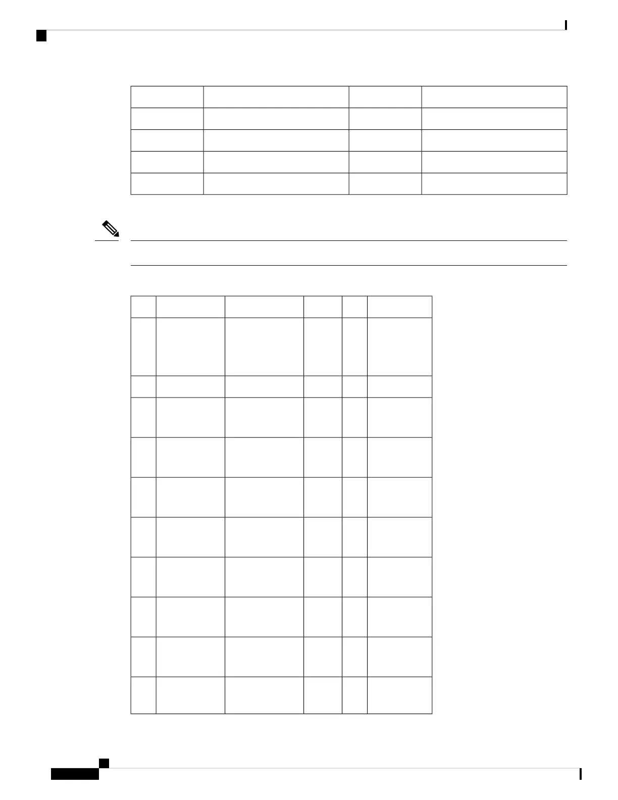
The following table lists the EIA/TIA-530 DTE cable pinouts. Arrows indicate signal direction.
Any pin not referenced is not connected.
Note
Table 44: EIA/TIA-530 DTE Cable Pinouts (DB-25 Male Connector)
SignalJ2DirectionDescriptionSignalJ1
–––Local connectionsMODE_2
MODE_0
MODE_DCE
J1-21
J1-23
J1-24
Shield GNDJ2-1–Shield––
BA(A), TxD+
BA(B), TxD–
J2-2
J2-14
——>
——>
Twisted pair no. 5O_TxD/RxD+
O_TxD/RxD–
J1-1
J1-14
BB(A), RxD+
BB(B), RxD–
J2-3
J2-16
<——
<——
Twisted pair no. 9I_RxD/TxD+
I_RxD/TxD–
J1-5
J1-18
CA(A), RTS+
CA(B), RTS–
J2-4
J2-19
——>
——>
Twisted pair no. 1O_RTS/CTS+
O_RTS/CTS–
J1-8
J1-9
CB(A), CTS+
CB(B), CTS–
J2-5
J2-13
<——
<——
Twisted pair no. 4I_CTS/RTS+
I_CTS/RTS–
J1-11
J1-10
CC(A), DSR+
AC; GND
J2-6<——
—
Twisted pair no.
10
I_DSR/DTR+
I_DSR/DTR–
J1-12
J1-25
CF(A), DCD+
CF(B), DCD–
J2-8
J2-10
<——
<——
Twisted pair no.
11
IO_DCD/DCD+
IO_DCD/DCD–
J1-6
J1-19
DB(A), TxC+
DB(B), TxC–
J2-15
J2-12
<——
<——
Twisted pair no. 7IO_TxC/RxC+
IO_TxC/RxC–
J1-3
J1-16
DD(A), RxC+
DD(B), RxC–
J2-17
J2-9
<——
<——
Twisted pair no. 8I_RxC/TxCE+
I_RxC/TxCE–
J1-4
J1-17
Cisco ASR 9000 Series Aggregation Services Router SIP and SPA Hardware Installation Guide
70
Overview: Cisco ASR 9000 Series Router Shared Port Adapters
4-Port Serial Interface SPA Cables, Connectors, and Pinouts
 Loading...


