1-11
Catalyst 3650 Switch Hardware Installation Guide
OL-29734-01
Chapter 1 Product Overview
Front Panel
• USB Type A connector
• USB mini-Type B (console) port
• LEDs
• Mode button
• UDI button
All the switches have similar components. See the following figures for examples.
Note The illustrations of the Catalyst 3650 switch are not intended to depict any particular color
scheme. They are provided as a reference for various features and markings described within this
guide.
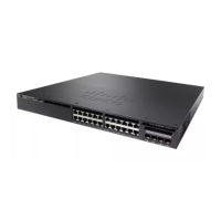
Figure 1-1 Catalyst 3650-48PD-L Switch Front Panel
Figure 1-2 Catalyst 3650-24PS-L Switch Front Panel
6
3
41
5
2
347809
0
1
X
1
3
X
1
2
X
2
4
X
2
5
X
3
6
X
3
7
X
4
8
X
A
CTV
C
ataly
st 365
0 48
P
oE+ 2X10G
TE
3
G
1
G
2
G
3
G
4
TE
4
1 Mode button 4 USB Type A storage port
2 Status LEDs 5 10/100/1000 PoE+ Ethernet ports
3 USB mini-Type B (console) port 6 Uplink ports
6
41
5
2
347615
3
2
4
X
0
1
X
1
3
X
1
2
X
C
ataly
st 365
0 48
P
oE
+ 2X10G
G
1
G
2
G
3
G
4
TE
3
TE
4

 Loading...


