EasyManuals Logo

Cisco Catalyst 3650 Series Hardware Installation Guide

Cisco Catalyst 3650 Series
126 pages
To Next Page IconTo Next Page
To Previous Page IconTo Previous Page
Page #87 background imageLoading...
Page #87 background image
4-11
Catalyst 3650 Switch Hardware Installation Guide
OL-29734-01
Chapter 4 Power Supply Installation
Installing a DC Power Supply
Figure 4-11 Crimping the Ground Lug
Step 5
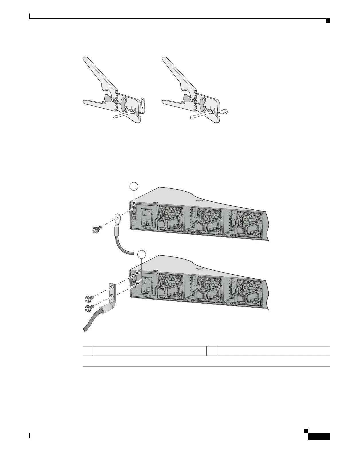
Use the ground screw to attach the single-hole ground lug to the switch’s rear panel. Use two ground
screws to attach the dual-hole lug to the switch’s rear panel (Figure 4-12).
Step 6 Using a ratcheting torque screwdriver, torque the ground-lug screws to 60 lbf-in. (960 ozf-in.).
Step 7 Connect the other end of the grounding wire to an appropriate grounding point at your site or to the rack.
Figure 4-12 Attaching the Ground Lug and Wire Assembly
334022
1 Single-hole ground screw and lug ring 2 Dual-hole ground adapter and dual-hole lug
347788
1
2
CO
NS
OLE
MGMT
CO
NS
OLE
MGMT

Table of Contents

Other manuals for Cisco Catalyst 3650 Series

Questions and Answers:

Question and Answer IconNeed help?

Do you have a question about the Cisco Catalyst 3650 Series and is the answer not in the manual?

Cisco Catalyst 3650 Series Specifications

General IconGeneral
RAM4 GB
Flash Memory4 GB
Ports24 or 48 10/100/1000 Ethernet ports
Uplinks4 x 1G SFP or 4 x 10G SFP+ (depending on model)
StackingUp to 9 switches with StackWise-160
Layer SupportLayer 2, Layer 3
SoftwareCisco IOS Software
Power SupplyInternal power supply; optional redundant power supply available
Storage Temperature-40°F to 158°F (-40°C to 70°C)

Related product manuals