EasyManuals Logo

Cisco Catalyst 4500e Series User Manual

Cisco Catalyst 4500e Series
152 pages
To Next Page IconTo Next Page
To Previous Page IconTo Previous Page
Page #90 background imageLoading...
Page #90 background image
4-16
Catalyst 4500 E-Series Switches Installation Guide
OL-13972-01
Chapter 4 Removing and Replacing FRUs
Replacing Backplane Modules
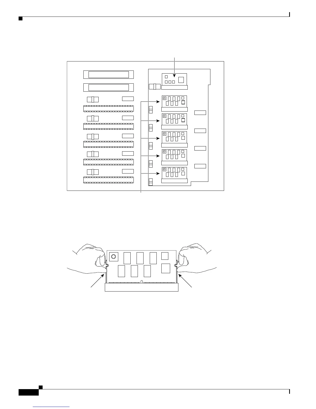
Figure 4-18 Catalyst 4507R-E Backplane
Step 4 If you are removing a clock module, remove the two screws that attach the module to the backplane.
Step 5 Find the seating levers on both sides of the connector for the module you wish to replace. (See
Figure 4-19.)
Figure 4-19 Finding the Seating Levers
Step 6 To release the module from its connector, pull the levers outward with your fingernails. The module will
pop out slightly. (See
Figure 4-20.)
Mux buffers
Clock module
130657
130658

Table of Contents

Questions and Answers:

Question and Answer IconNeed help?

Do you have a question about the Cisco Catalyst 4500e Series and is the answer not in the manual?

Cisco Catalyst 4500e Series Specifications

General IconGeneral
SeriesCatalyst 4500E Series
StackableNo
Chassis Options3-slot, 6-slot, 7-slot, 10-slot
Power Supply OptionsAC, DC
RedundancyPower supply redundancy, supervisor engine redundancy (1+1)
Layer SupportLayer 2
VirtualizationYes (Virtual Switching System - VSS)
Form FactorModular
PortsGigabit Ethernet, 10 Gigabit Ethernet, 40 Gigabit Ethernet, and 100 Gigabit Ethernet options depending on the line cards
Jumbo Frame SupportYes
FeaturesFlexible NetFlow, TrustSec
Maximum Port DensityUp to 384 ports per chassis
Operating SystemCisco IOS XE
ManagementCLI, SNMP, Cisco Prime Infrastructure, Cisco DNA Center
Security Features802.1X
VLAN SupportUp to 4096 VLANs
QoS SupportYes
Supervisor Engine OptionsSup8-E

Related product manuals