EasyManuals Logo

Cisco Catalyst 4500e Series User Manual

Cisco Catalyst 4500e Series
152 pages
To Next Page IconTo Next Page
To Previous Page IconTo Previous Page
Page #91 background imageLoading...
Page #91 background image
4-17
Catalyst 4500 E-Series Switches Installation Guide
OL-13972-01
Chapter 4 Removing and Replacing FRUs
Replacing Backplane Modules
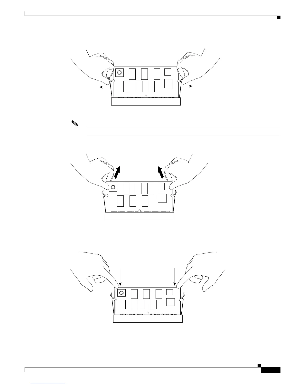
Figure 4-20 Releasing the Module
Step 7 Pull out the module while holding the top left and top right corners. (See Figure 4-21.)
Note When handling the modules, do not touch the chips or the gold edge contacts on the module.
Figure 4-21 Removing the Module
Step 8 Put the replacement module in at roughly a 30 degree angle, and gently push the module down. Make
sure you apply force evenly on the left and right. (See
Figure 4-22.)
Figure 4-22 Seating the Replacement Module
Step 9 Make sure the module is fully seated. (See Figure 4-23.)
130659
130660
130661

Table of Contents

Questions and Answers:

Question and Answer IconNeed help?

Do you have a question about the Cisco Catalyst 4500e Series and is the answer not in the manual?

Cisco Catalyst 4500e Series Specifications

General IconGeneral
SeriesCatalyst 4500E Series
StackableNo
Chassis Options3-slot, 6-slot, 7-slot, 10-slot
Power Supply OptionsAC, DC
RedundancyPower supply redundancy, supervisor engine redundancy (1+1)
Layer SupportLayer 2
VirtualizationYes (Virtual Switching System - VSS)
Form FactorModular
PortsGigabit Ethernet, 10 Gigabit Ethernet, 40 Gigabit Ethernet, and 100 Gigabit Ethernet options depending on the line cards
Jumbo Frame SupportYes
FeaturesFlexible NetFlow, TrustSec
Maximum Port DensityUp to 384 ports per chassis
Operating SystemCisco IOS XE
ManagementCLI, SNMP, Cisco Prime Infrastructure, Cisco DNA Center
Security Features802.1X
VLAN SupportUp to 4096 VLANs
QoS SupportYes
Supervisor Engine OptionsSup8-E

Related product manuals