15-5
Catalyst 6500 Series Switch and Cisco 7600 Series Router Firewall Services Module Configuration Guide
OL-6392-01
Chapter 15 Using Failover
Understanding Failover
traffic you expect to be inspected by the FWSM. The FWSM has an internal 6-Gbps EtherChannel to the
switch, so if the FWSM runs at full capacity, the trunk between the two devices needs to include at least
six 1-Gbps interfaces. EtherChannel aggregates the bandwidth of up to eight compatibly configured
ports into a single logical link. (See the “Adding a Trunk Between a Primary Switch and Secondary
Switch” section on page 2-12 for more information.)
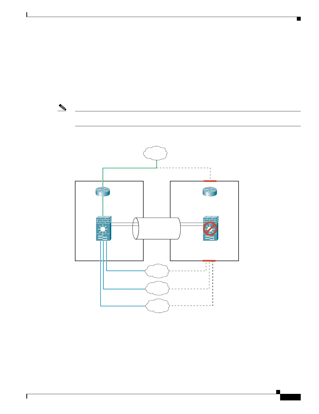
Figure 15-2 shows a typical switch and FWSM redundancy configuration. The Spanning Tree algorithm
ensures that the VLANs pass through only one switch, which also contains the active FWSM. The trunk
between the two switches carries all FWSM VLANs, including the failover and state links (VLANs 10
and 11).
Note The FWSM failover is independent of the switch failover operation; however, the FWSM works in any
switch failover scenario.
Figure 15-2 Normal Operation with Standby Modules
Active
FWSM
VLAN 200
VLAN 100
VLAN 201
Mktg
Inside
Eng
Active Switch
Standby
FWSM
Standby Switch
Trunk:
VLANs 200, 201,
202, 203, 10, 11
Internet
VLAN 202
VLAN 11
VLAN 10
Failover Links:
VLAN 203
104652