RJ-45 Console Port StatusColor
RJ-45 console is enabled. USB console is disabled.Green
Fan LED
Table 31: Fan LED Indicator
DescriptionColor/State
The fan is not receiving power; the fans have stopped.Off
All fans are operating normally.Green
One or more fans have encountered tachometer faults.Amber
One or more fans' tachometer faults have exceeded the maximum limit.Red
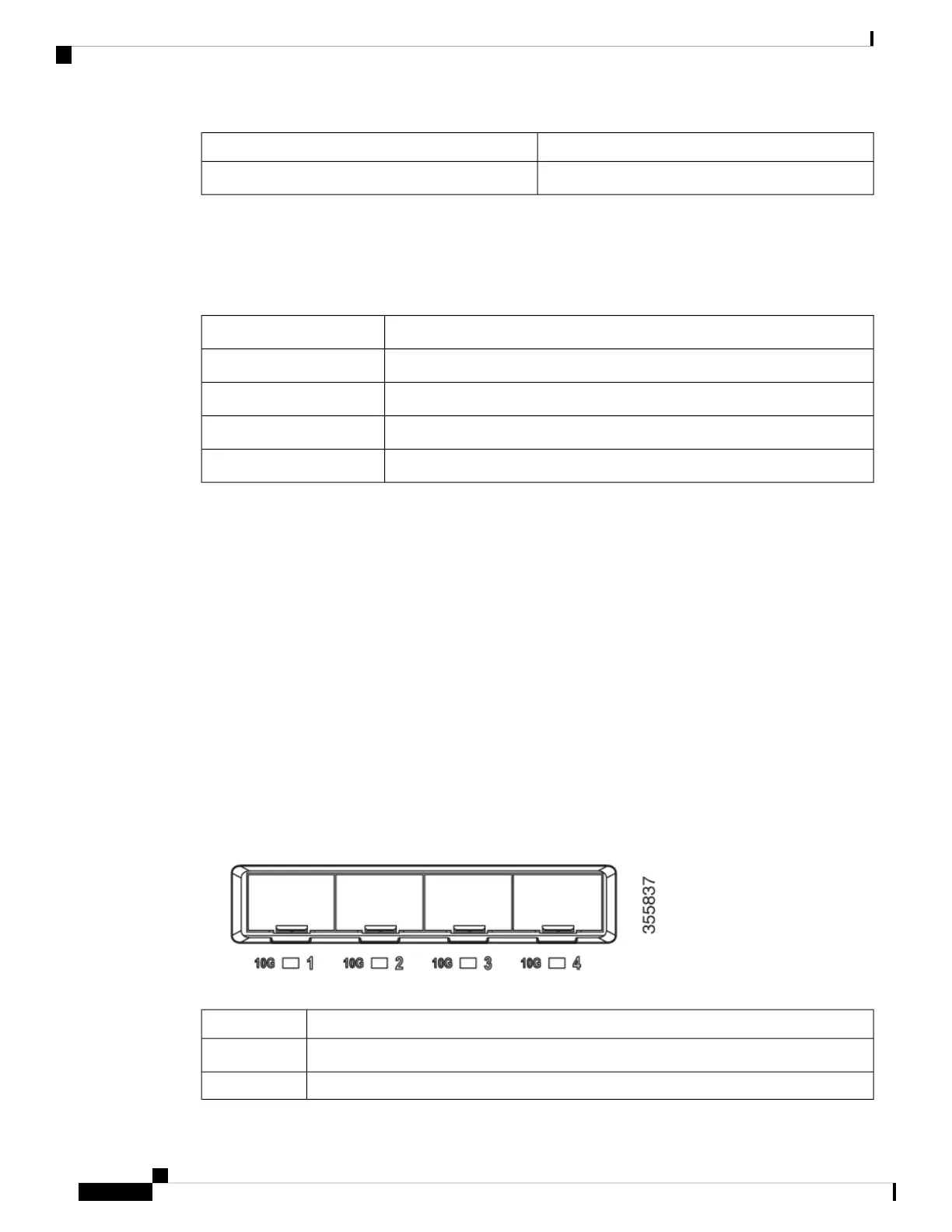
Uplink Port LEDs
The uplink ports have various status LEDs. Each port LED is labeled according to its module status.
• For SFP ports, a G labeling nomenclature is used, where G = 1 Gigabit. The The G label appears to the
left of the uplink port LED.
• For SFP+ ports, a 10G labeling nomenclature is used, where 10G = 10 Gigabit. The 10G label appears
to the left of the uplink port LED. SFP+ module ports support both SFP+ and SFP modules
• For SFP28 ports, a 25G labeling nomenclature is used, where 25G = 25 Gigabit. The The G label appears
to the left of the uplink port LED.
• For QSFP+ ports, a 40G labeling nomenclature is used, where 40G = 40 Gigabit. The The G label appears
to the left of the uplink port LED.
Figure 66: SFP+ Port LEDs
Network Module Link StatusColor
Link is off.Off
Link is on; no activity.Green
Cisco Catalyst 9200 Series Switches Hardware Installation Guide
116
Switch LEDs
Fan LED

 Loading...


