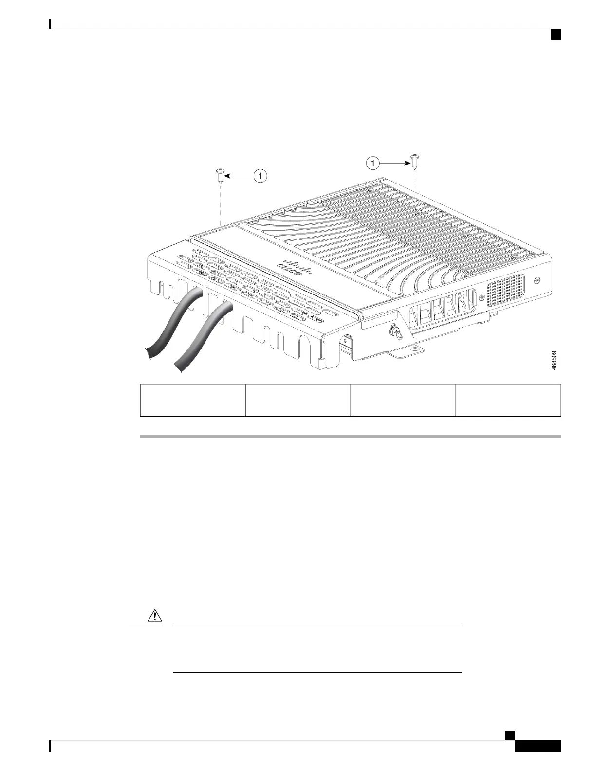
Step 3 Guide the connected cables through the slots in the front of the cable guard and pivot the cable guide back to
the original position as shown in the following figure.
Step 4 Lock the cable guide in the installed position using the two 8-18 Phillips pan-head screws provided.
Figure 47: Switch with Cable Guide Installed
--Two 8-18 Phillips
pan-head screws
1
Installing an SFP or SFP+ Module
Before you begin
When installing SFP or SFP+ modules, observe these guidelines:
• Do not remove the dust plugs from the modules or the rubber caps from the fiber-optic cable until you
are ready to connect the cable. The plugs and caps protect the module ports and cables from contamination
and ambient light.
• To prevent ESD damage, follow your normal board and component handling procedures when connecting
cables to the switch and other devices.
Removing and installing an SFP or SFP+ module can shorten its useful life.
Do not remove and insert any module more often than is absolutely
necessary.
Caution
Cisco Catalyst 9200 Series Switches Hardware Installation Guide
73
Installing a Compact Switch
Installing an SFP or SFP+ Module

 Loading...


