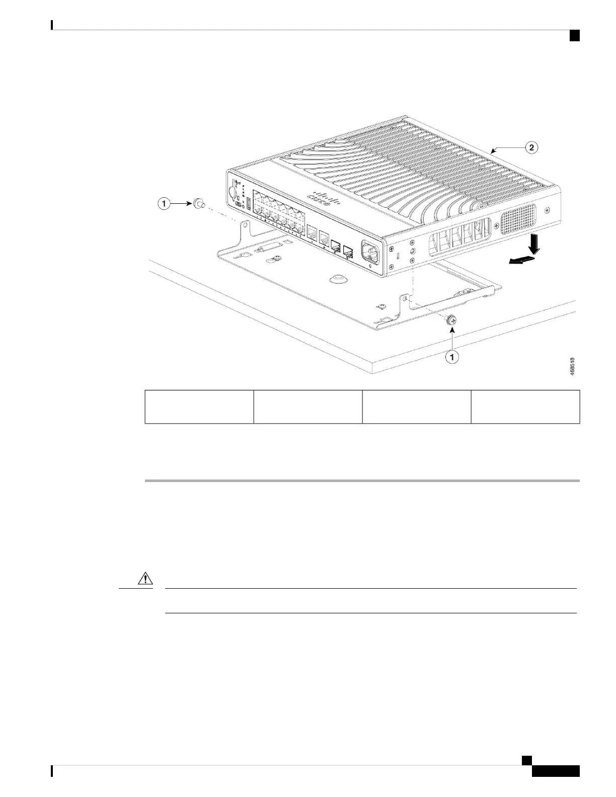
Figure 25: Securing the Switch to the Mounting Tray
Switch2Two 10-32 Phillips
pan-head screws
1
To prevent airflow restriction, allow clearance around the ventilation openings to be at least: 3 in.
(7.6 cm) Statement 1076
Warning
Mounting using the Mounting Tray and Magnet
This topic expains the steps to use a magnet with the mounting tray to mount the switch on a metal surface.
The illustrations used in the procedure shows how to mount the switch on a metal desk. You can use a similar
procedure to mount the switch on a metal wall or under a metal desk.
Do not use the magnet without a mounting tray.
Caution
Before you begin
Ensure you have the following accessories available.
• Mounting tray and magnet for compact switches (C9K-MGNT-TRAY)
• Two 10-32 Phillips pan-head screws
Cisco Catalyst 9200 Series Switches Hardware Installation Guide
55
Installing a Compact Switch
Mounting using the Mounting Tray and Magnet

 Loading...


