Replacing a 2 (RU) Fan Module
Before You Begin
•
Verify that you have an ESD wrist strap or other device to prevent ESD damage for components that
you touch.
•
Verify that you have an antistatic surface or bag for placing the fan module that you remove from the
chassis.
•
Verify that the replacement fan module has the correct direction of airflow (it has the same coloring as
the other fan and power supply modules in the same chassis).
Procedure
Step 1
Remove the fan module that you are replacing as follows:
a) Loosen the captive screws on the fan module by turning them counterclockwise, using a flat-blade or
number 2 Phillips screwdriver if required.
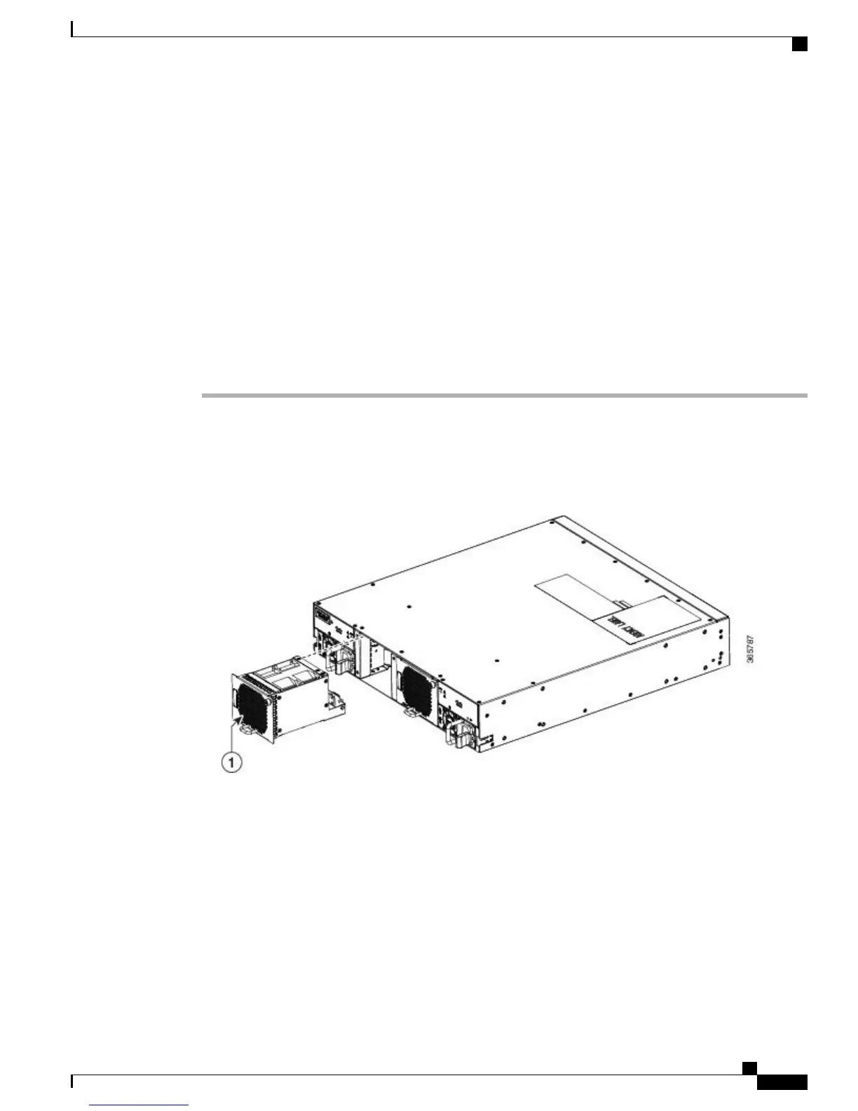
Figure 18: Replacing Fan Module on NCS 5002
b) Grasp the captive screws of the fan module and pull it outward.
c) Pull the fan module clear of the chassis and set it on an antistatic surface or repack it in packing materials.
Step 2
Install the replacement fan module as follows:
a) Hold the fan module with the sheet metal flange holding the connector on the bottom.
b) Place the fan module into the front chassis cavity so it rests on the chassis, and then push the fan module
into the chassis as far as it can go until the captive screw makes contact with the chassis.
c) Tighten the captive screw.
Hardware Installation Guide for Cisco NCS 5000 Series Routers
35
Replacing NCS 5000 Router Components
Replacing a 2 (RU) Fan Module
 Loading...


