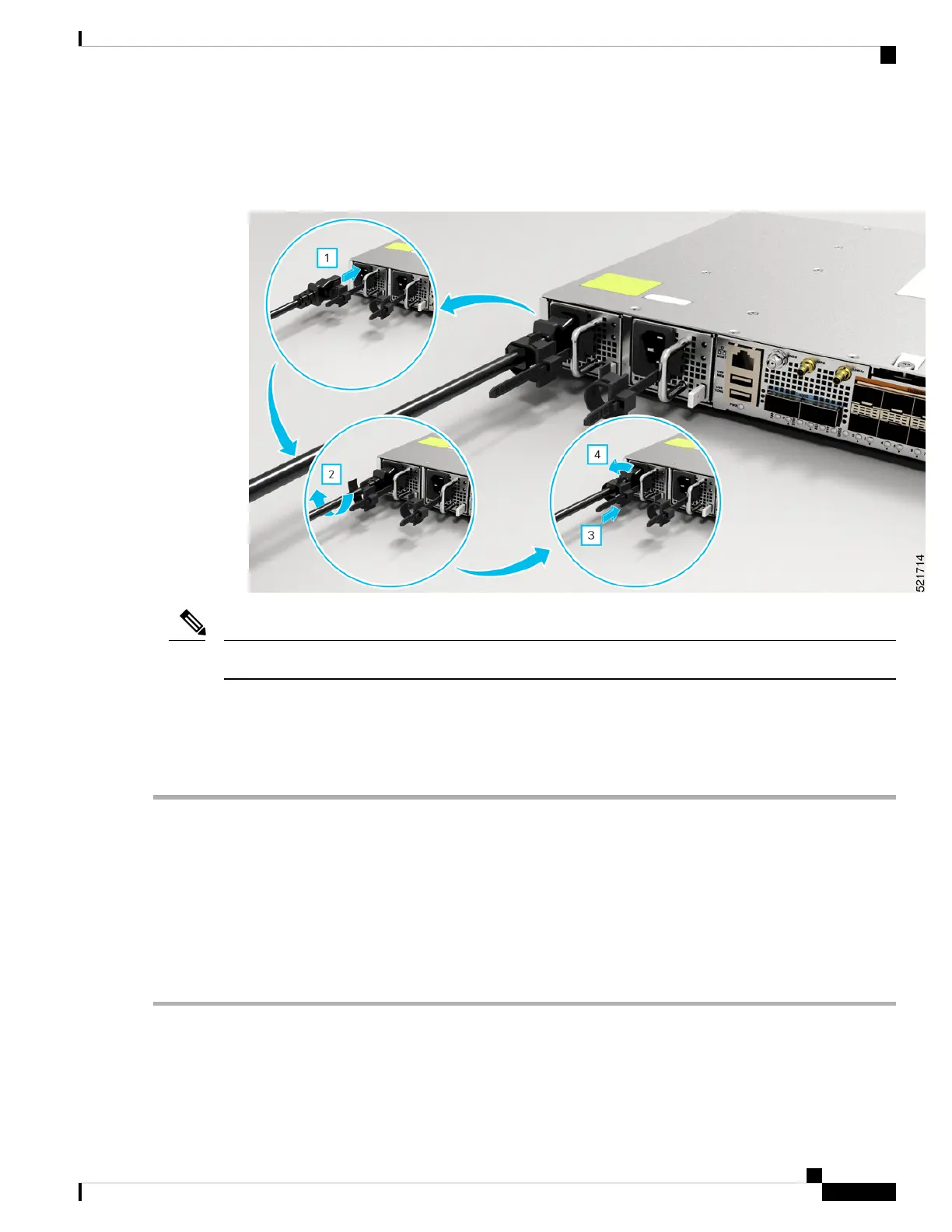
2. Insert the power supply cord into the tie [1, 3] and tighten the tie around the power supply cord as shown
in [2, 4] in the figure below.
Figure 19: Attach the AC Power Tie-and-Clip Cord
These images are for only representation purposes.
Note
Activate an AC Power Supply Module
Perform the following procedure to activate an AC power supply:
Step 1 Plug the power cord into the power supply.
Step 2 Connect the other end of the power cord to an AC-input power source.
Step 3 Verify power supply operation by checking if the respective power supply front panel LED (PS0 or PS1) is green.
Step 4 If the LEDs indicate a power problem, see Troubleshooting for troubleshooting information.
Step 5 If you are also connecting a redundant AC power supply, repeat these steps for the second power source.
If you are connecting a redundant AC power supply, ensure that each power supply is connected to a separate
power source in order to prevent power loss in the event of a power failure.
Note
Cisco Network Convergence System 540 Large Density Routers Hardware Installation Guide
37
Install the Device
Activate an AC Power Supply Module

 Loading...


