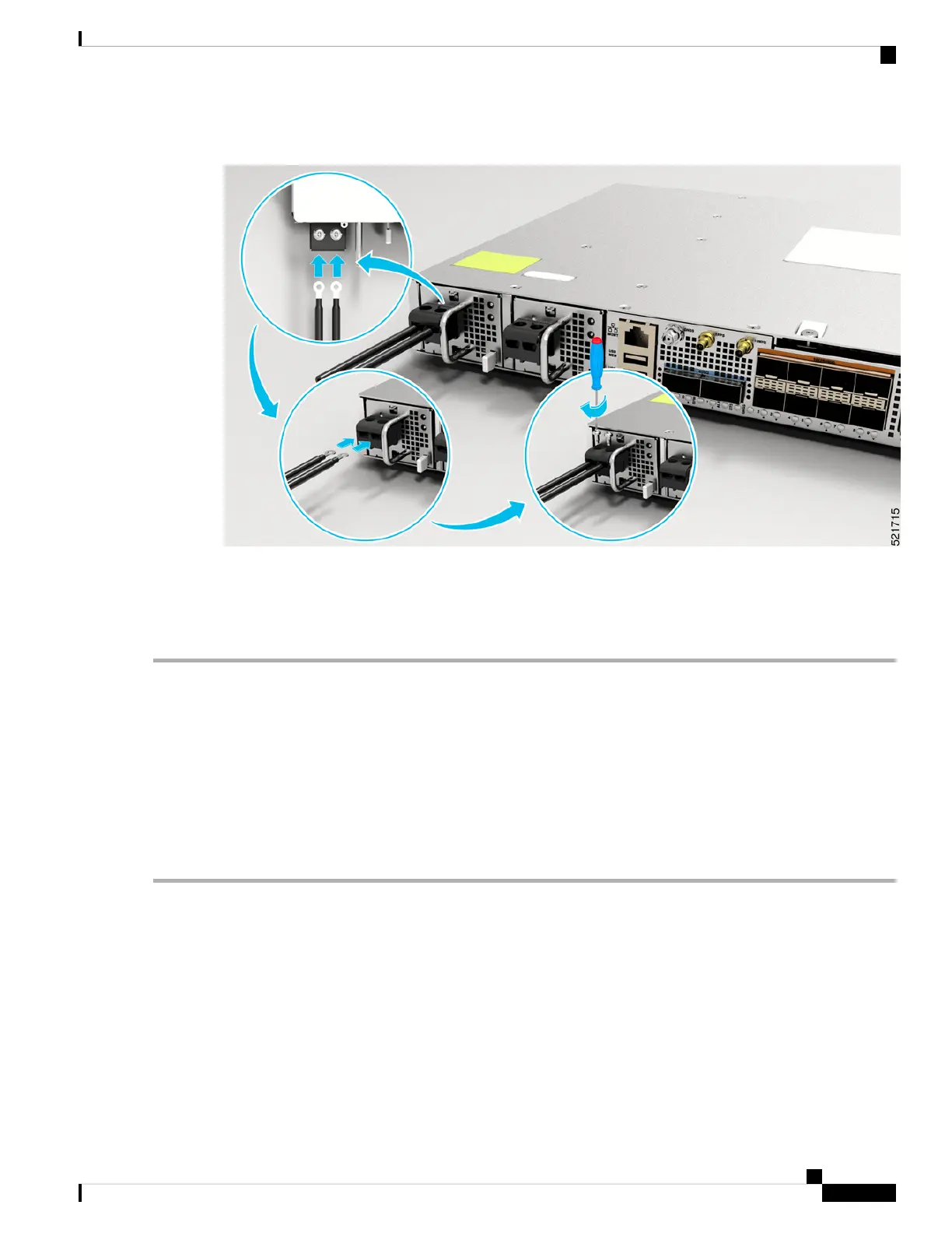
Figure 21: Attach the DC Power Supply Wires
Activate a DC Power Supply Module
Perform the following procedure to activate a DC power supply:
Step 1 Remove the tape from the circuit-breaker router handle, and restore power by moving the circuit-breaker router handle
to the On (|) position.
Step 2 Verify the power supply operation by checking whether the respective power supply front panel LED (PS0 or PS1) is
green.
Step 3 If the LEDs indicate any issues with power problem, see Troubleshooting.
Step 4 If you are also connecting a redundant DC power supply, repeat these steps for the second power source.
If you are connecting a redundant DC power supply, ensure that each power supply is connected to a separate
power source in order to prevent power loss in the event of a power failure.
Note
Port Connection Guidelines
Depending on the chassis and installed line cards, you can use pluggables QSFP56-DD, QSFP28-DD, QSFP28,
QSFP, SFP56, SFP28, SFP10, SFP, USB console, and RJ-45 connectors to connect the ports on the line cards
to other network devices.
To prevent damage to the fiber-optic cables, we recommend that you keep the transceivers disconnected from
their fiber-optic cables when installing the transceiver in the line card. Before removing a transceiver from
the router, remove the cable from the transceiver.
Cisco Network Convergence System 540 Large Density Routers Hardware Installation Guide
39
Install the Device
Activate a DC Power Supply Module

 Loading...


