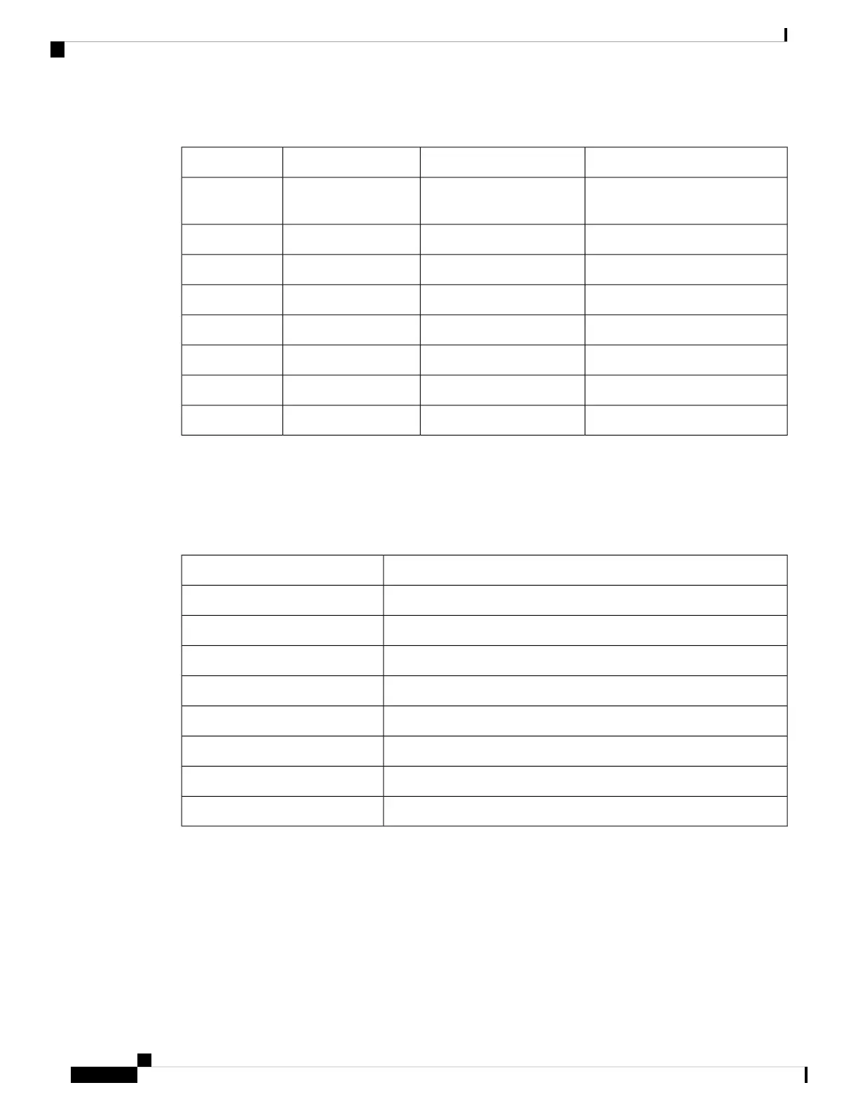
Table 13: Console Port Pinouts
DescriptionDirectionSignal NamePin
Aux Consoles transmit output,
RS232
OutputACONS-TX1
Receive TIP (T1/E1)NANC2
Console RS232 transmitOutputCONS-TX3
GroundNAGnd4
GroundNAGnd5
Console RS232 receiveInputCONS-RX6
Aux Consoles receive input, RS232InputACONS-RTX7
NANANC8
Management Ethernet Port Pinouts
This following table summarizes the Management Ethernet port pinouts:
Table 14: Management and PTP Ethernet Port Pinouts
Signal NamePin
TRP0+1
TRP0-2
TRP1+3
TRP1-4
TRP2+5
TRP2-6
TRP3+7
TRP3-8
Timing Port Pinouts
The platform is capable of receiving or sourcing timing signals of 1 PPS & 10 MHz. These interfaces are
provided by two mini-coax 50-Ohm, 1.0/2.3 DIN series connector on the front panel. Similarly there are two
mini-coax 50-Ohm connectors provided in the front panel to output this 1PPS and 10MHz.
This table below summarizes the timing port pinouts:
Cisco Network Convergence System 540 Large Density Routers Hardware Installation Guide
70
Appendix
Management Ethernet Port Pinouts

 Loading...


