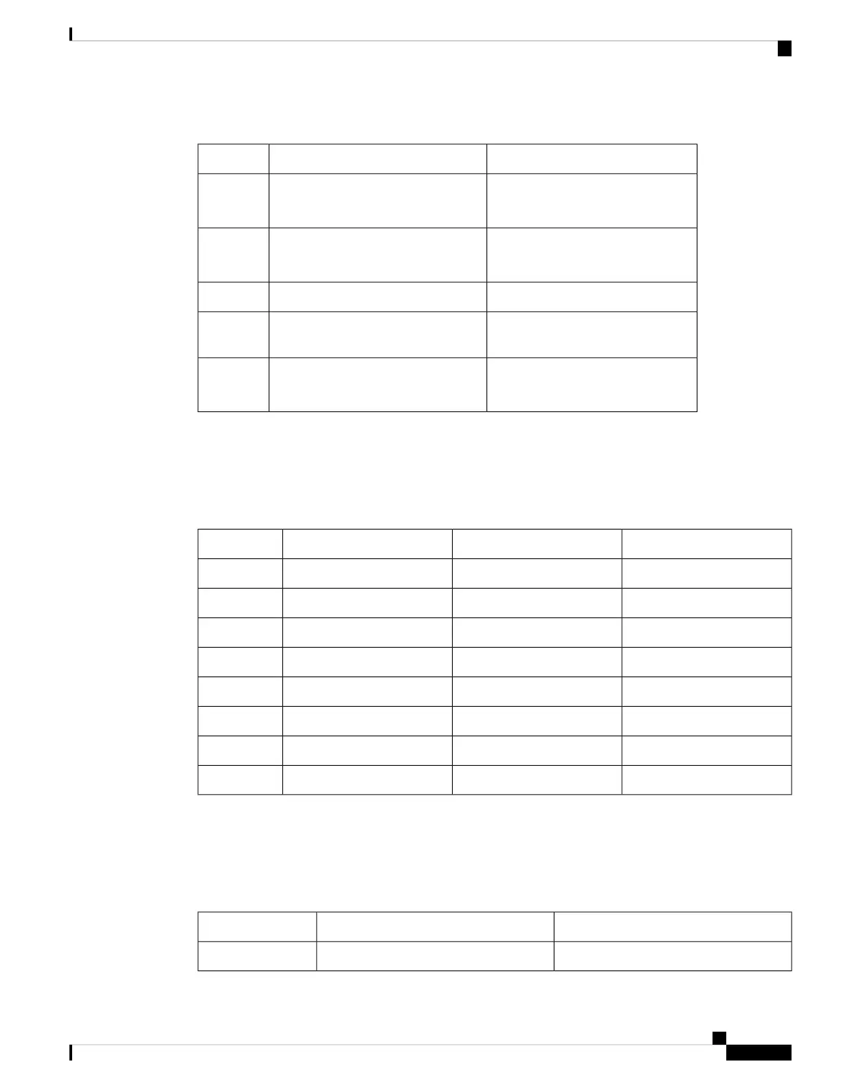
Table 15: Timing Port Pinouts
1PPS (Input and Output)10 MHz (Input and Output)
Input—Rectangular pulse
Output—Rectangular pulse
Input—Sine wave
Output—Square wave
Waveform
Input— > 2.4 volts TTL compatible
Output— > 2.4 volts TTL compatible
Input— > 1.7 volt p-p(+8 to +10 dBm)
Output— > 2.4 volts TTL compatible
Amplitude
50 ohms50 ohmsImpedance
26 microseconds50% duty cyclePulse
Width
40 nanosecondsInput—AC coupled
Output—5 nanoseconds
Rise Time
Time-of-Day Port Pinouts
This table summarizes the ToD/1-PPS port pinouts:
Table 16: RJ-45 ToD/1-PPS Port Pinouts
DescriptionDirectionSignal NamePin
–––1
–––2
1PPS RS422 signalOutput or Input1PPS_N3
––GND4
––GND5
1PPS RS422 signalOutput or Input1PPS_P6
Time-of-Day characterOutput or InputTOD_N7
Time-of-Day characterOutput or InputTOD_P8
USB Port Pinouts
This following table summarizes the USB port pinouts:
Table 17: USB Port Pinouts
DescriptionSignal NamePin
+5 VDCVccA1
Cisco Network Convergence System 540 Large Density Routers Hardware Installation Guide
71
Appendix
Time-of-Day Port Pinouts

 Loading...


