10-91
Cisco Nexus 7000 Series Hardware Installation and Reference Guide
OL-23069-07
Chapter 10 Installing or Replacing Components
Replacing the Front Door and Air Intake Assemblies on the Cisco Nexus 7018 Chassis
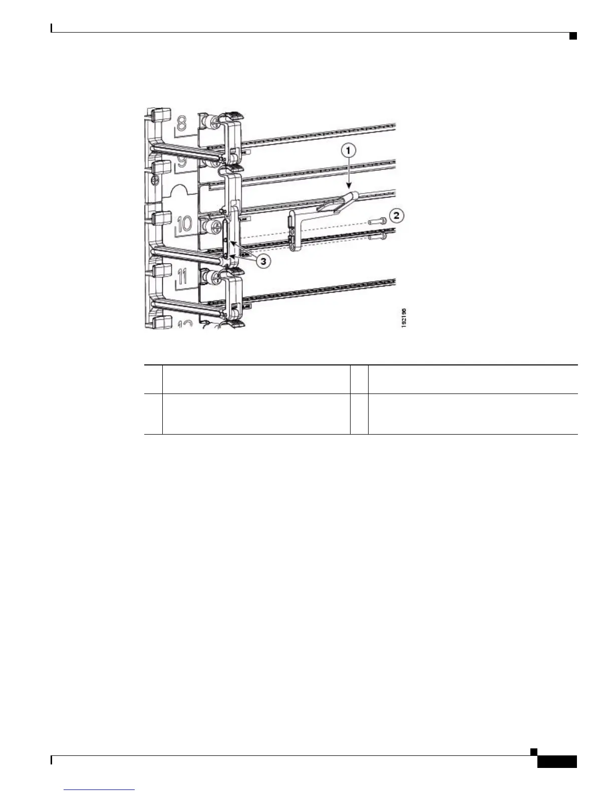
Figure 10-43 Attaching the Left Door Stopper
Step 3
Position the right door stopper (has an R on its base) on the middle of the right side of the cable
management frame and fasten it with two M3x14 pan-head screws as shown in Figure 10-44. Tighten
these two screws to 8.4 to 11 in-lb (0.9 to 1.2 N·m).
1 Left door stopper identified with an L on
the bottom of the base.
3 Screw holes on the cable management assembly.
2 Two M3x14 screws that fasten the stopper
to the left side of the cable management
assembly.

 Loading...


