D-6
Cisco Nexus 7000 Series Hardware Installation and Reference Guide
OL-23069-07
Appendix D Chassis and Module LEDs
Fabric Module LEDs
Fabric Module LEDs
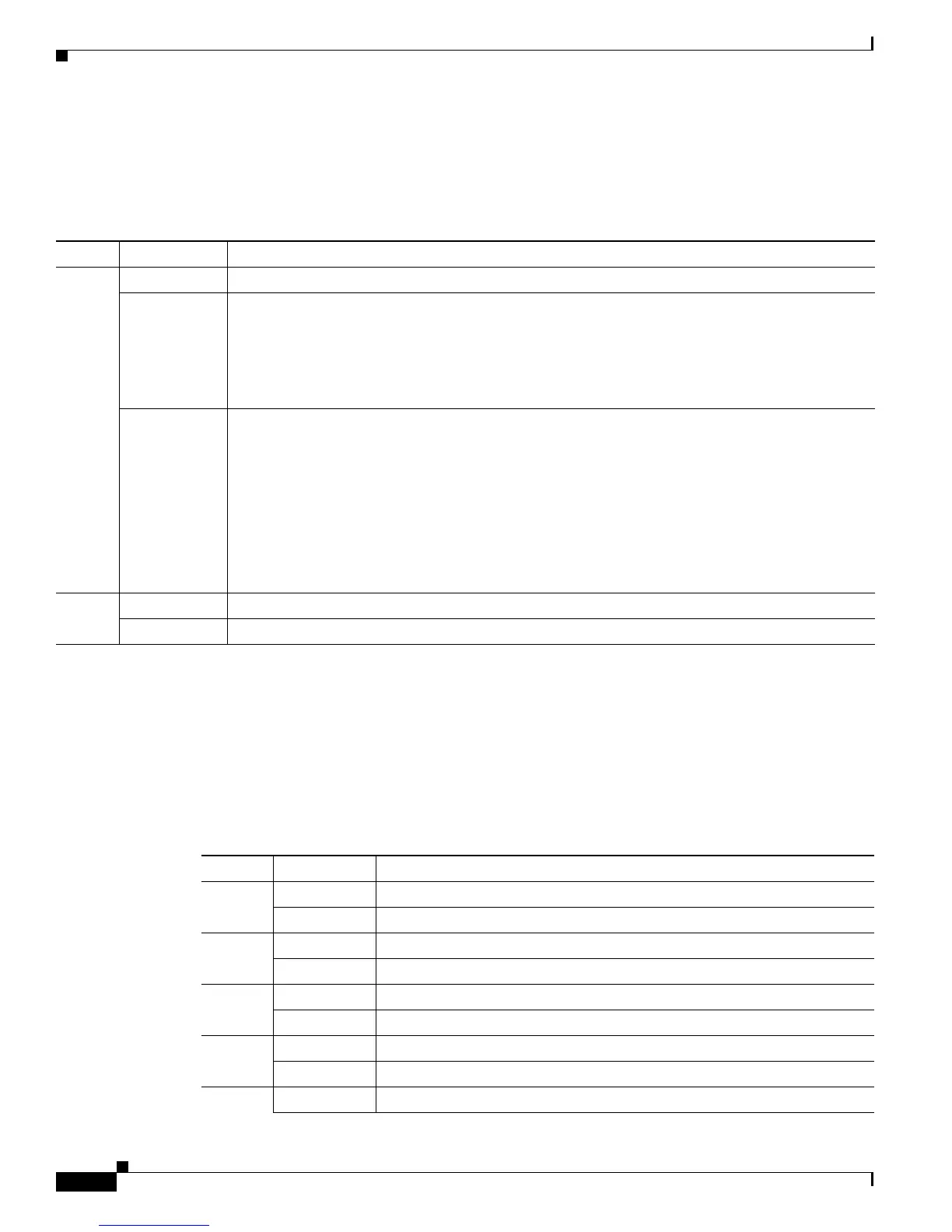
Table D-5 describes the fabric module LEDs.
Power Supply LEDs
Table D-6 describes the power supply unit LEDs. Depending on the power supply (both AC and DC
power supplies), there are 1, 2, or 4 input LEDs. The Output, Fault, and ID LEDs have the same function
for both the AC and DC power supply units.
Table D-5 Fabric Module LEDs
LED Status Description
Status Green All diagnostics pass. The module is operational (normal initialization sequence).
Red The diagnostic test has failed. The module is not operational because a fault has occurred during
the initialization sequence.
or
The inlet air temperature of the system has exceeded the safe operating temperature limits of the
card (a major environmental warning). The card has been shut down to prevent permanent damage.
Flashing red The fabric module has just been inserted and is booting up.
or
An overtemperature condition has occurred and the module has powered down.
or
The power was turned off with a CLI command.
or
The module is resetting and both ejector levers are out.
ID Flashing blue The operator has activated this LED to identify this module in the chassis.
Off This module is not being identified.
Table D-6 Power Supply LEDs
LED Color Condition
Input 1 Green The AC or DC input voltage is within the valid range.
Off The AC or DC input voltage is outside the valid range.
Input 2 Green The AC or DC input voltage is within the valid range.
Off The AC or DC input voltage is outside the valid range.
Input 3 Green The DC input voltage is within the valid range.
Off The DC input voltage is outside the valid range.
Input 4 Green The DC input voltage is within the valid range.
Off The DC input voltage is outside the valid range.
Output Green The AC or DC output power is within the valid range.

 Loading...


