3-10
Cisco Nexus 7000 Series Hardware Installation and Reference Guide
OL-23069-07
Chapter 3 Installing a Cisco Nexus 7009 Chassis
Installing the Bottom-Support Rails on the Rack
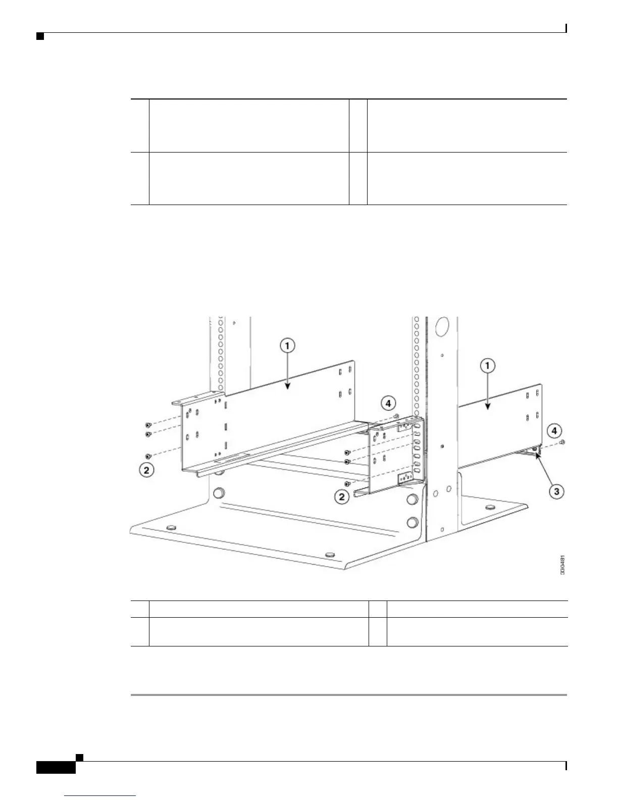
Step 2 Use a Phillips screwdriver to screw in two or three (three are recommended if you have three screw holes)
M6 x 19 mm or 12-24 x 3/4 inch Phillips screws on each bracket (using a total of 6 screws for both
brackets) as shown in Figure 3-4.
Figure 3-4 Attaching a Center-Mount Bottom-Support Rail to a Rack
Step 3
Align the crossbar to the lower back of the two bottom-support rails and use two M4 x 8 mm screws to
attach it to each rail (one screw for each rail).
1 For the first and heaviest Cisco Nexus 7009
chassis installed in a rack, position two
center-mount bottom-support rails at the
lowest RU on the rack.
3 Allow at least 26.25 inches (66.7 cm) (15 RU)
for each Cisco Nexus 7009 system.
2 For the second Cisco Nexus 7009 chassis
installed in a rack, position two center-mount
bottom-support rails immediately above the
first installed switch.
1 Left and right center-mount bottom-support rails 3 Crossbar
2 Two sets of 3 M6 x 19 mm Phillips screws or
two sets of 3 12-24 x 3/4 in. Phillips screws
4 M4 x 8 mm Phillips screws (2)

 Loading...


