1-140
Cisco ONS 15454 SDH Troubleshooting Guide, R5.0
July 2005
Chapter 1 General Troubleshooting
1.12.2 Faulty Fiber-Optic Connections
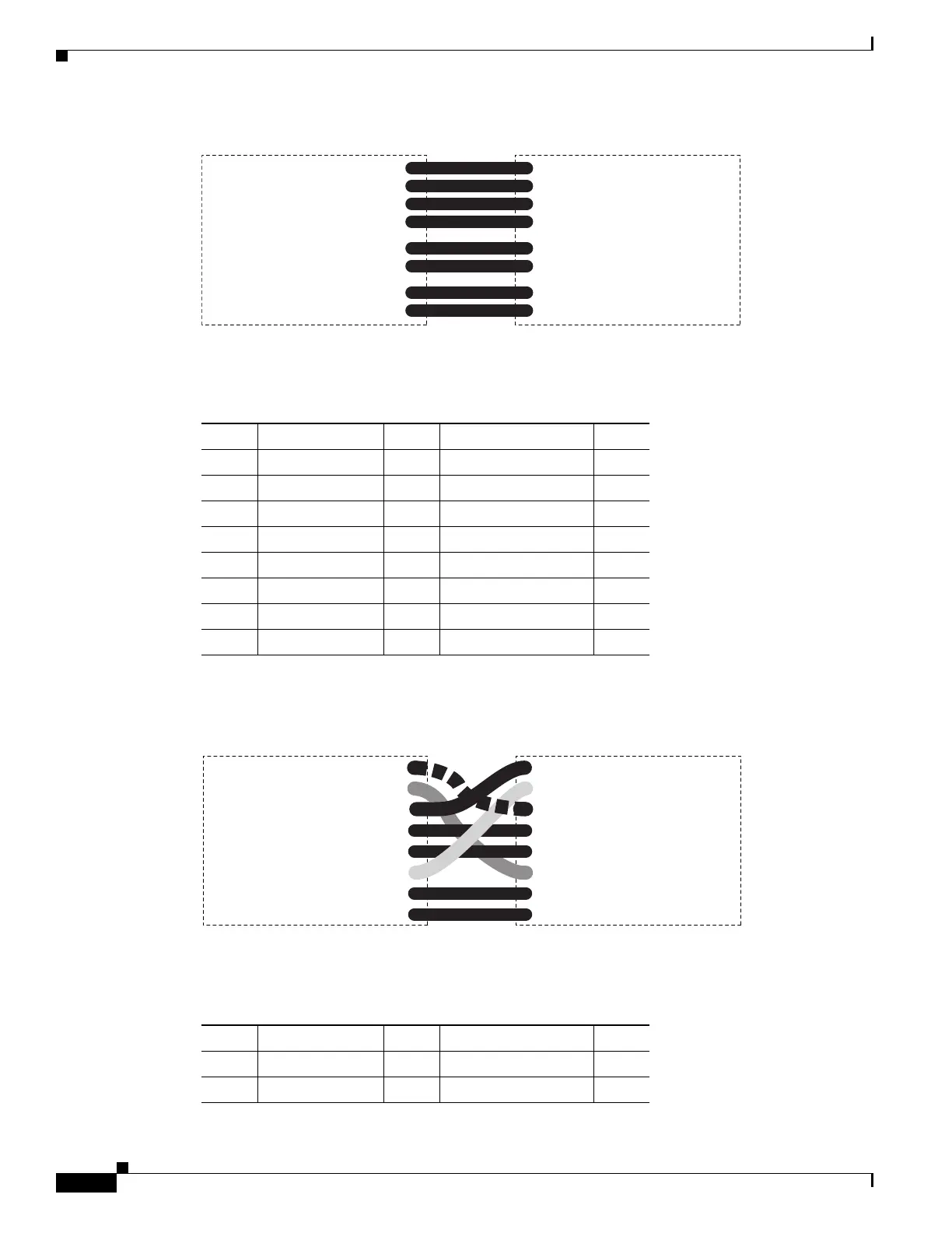
Figure 1-53 LAN Cable Layout
Table 1-5 provides the LAN cable pinouts.
Figure 1-54 shows a cross-over cable layout.
Figure 1-54 Cross-Over Cable Layout
Table 1-6 provides cross-over cable pinouts.
1
2
3
4
5
6
7
8
1
2
3
4
5
6
7
8
55415
Table 1-5 LAN Cable Pinout
Pin Color Pair Name Pin
1 white/orange 2 Transmit Data + 1
2 orange 2 Transmit Data – 2
3 white/green 3 Receive Data + 3
4blue 1— 4
5 white/blue 1 — 5
6 green 3 Receive Data – 6
7 white/brown 4 — 7
8brown 4— 8
1
2
3
4
5
6
7
8
1
2
3
4
5
6
7
8
55416
Table 1-6 Cross-Over Cable Pinout
Pin Color Pair Name Pin
1 white/orange 2 Transmit Data + 3
2 orange 2 Transmit Data – 6