1-33
Cisco ONS 15454 Procedure Guide, R4.0
March 2003
Chapter 1 Install the Shelf and Backplane Cable
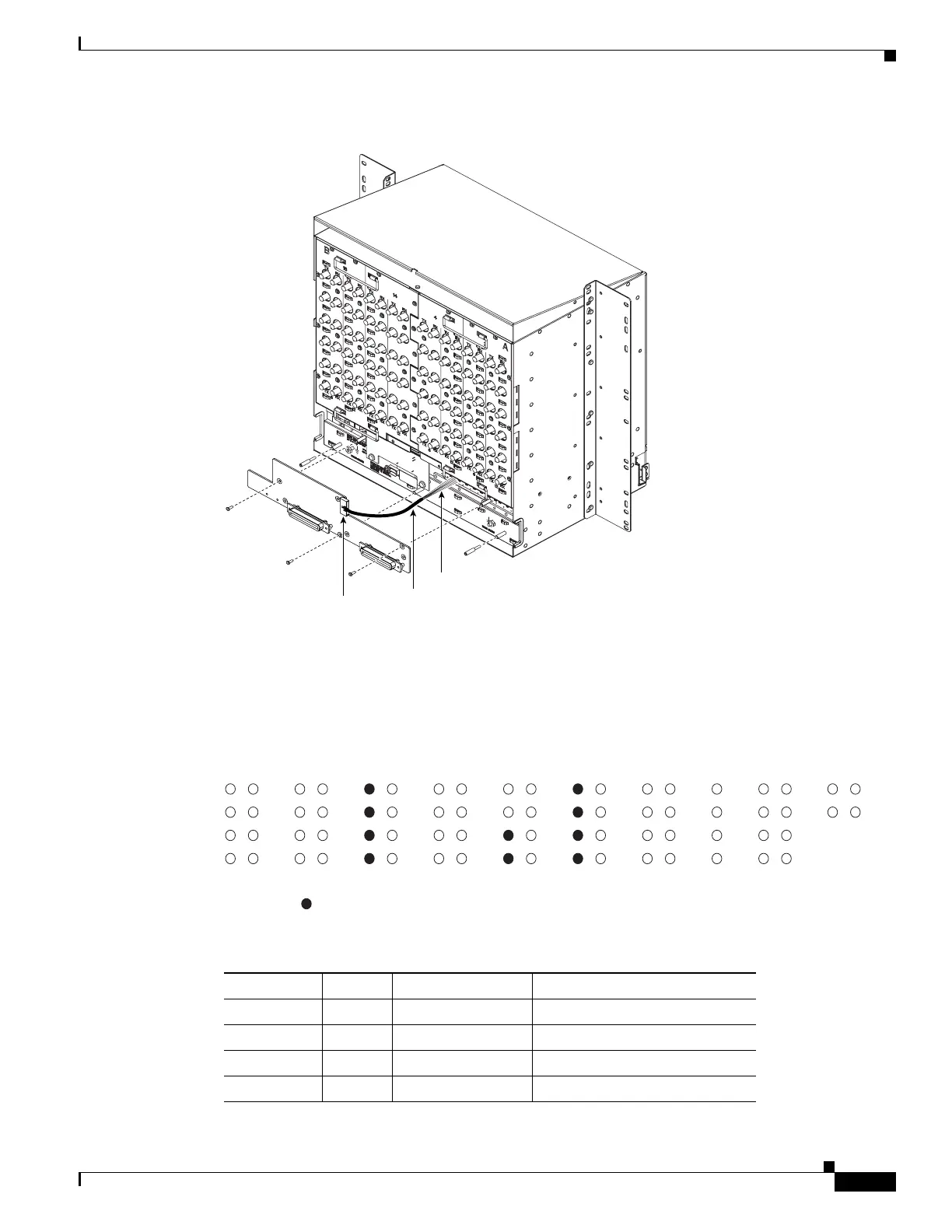
NTP-A119 Install the Alarm Expansion Panel
Figure 1-13 Installing Standoffs and the AEP
Step 4
Insert and tighten three screws to secure the AEP to the backplane.
Step 5 Attach the open ends of the wires from the AEP board to the wire-wrap pins on the backplane of the shelf
(Figure 1-14). Table 1-1 lists the AEP pin assignments.
Figure 1-14 AEP Wire-Wrap Connections to Backplane Pins
78403
AEP cable
Connector
Wires
Table 1-1 Pin Assignments for the AEP
Wire Pin AEP Signal AIC-I Signal
Tip 1 7 AEP_GND GND
Tip 2 8 AEP_+5 AE_+5
Tip 3 9 VBAT- VBAT-
Tip 4 10 VB+ VB+
BITS LAN IN IN/OUT IN IN MODEM CFT LOCAL IN
TIP RNG TIP RNG TIP RNG TIP RNG TIP
RNG TIP RNG TIP RNG
1
2
3
4
1
2
3
4
5
6
7
8
9
10
11
12
13
used for connection of AIC-I and AEP
78472

 Loading...


