6-15
Cisco SCE8000 GBE Installation and Configuration Guide
Chapter 6 Cabling the Line Ports and Completing the Installation
Cabling the 10 GBE Line Interface Ports: Using the External Optical Bypass Module
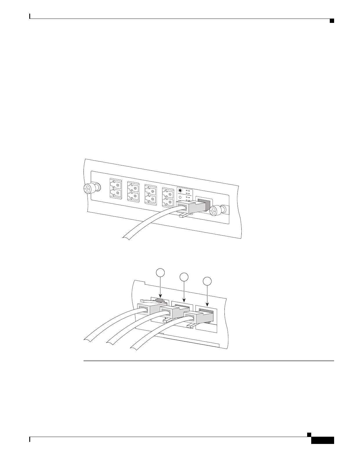
Step 3 Using the control cable provided, which has RJ11 connectors on both ends, plug one end into the CTRL
interface on the external bypass module (see Figure 6-3) and plug the other end into the External Bypass
interface on the Cisco SCE 8000-SCM-E in slot 1 of the Cisco SCE 8000 chassis (see item 1 in
Figure 6-4). If using only one external bypass module, use External Bypass port 1. If using two external
bypass modules, use both External Bypass ports on the Cisco SCE 8000-SCM-E in slot 1.
Step 4 Complete the installation and powering up of the Cisco SCE 8000.
By its nature, the optic bypass module does not connect the link to the Cisco SCE 8000-SIP module until
the entire Cisco SCE 8000 system is fully functional. It is necessary to bring the Cisco SCE 8000 to fully
operational and non-bypassed status to confirm correct functioning of the link through the optic bypass
module to the Cisco SCE 8000-SIP module.
Step 5 Verify link connectivity by checking that the link LED on the 10 GBE interface is green, or by using the
Cisco SCE 8000 command line.
Figure 6-3 Cabling the CTLR Interface on the External Bypass Module
Figure 6-4 Cabling the Cisco SCE 8000-SCM-E Module
270977
TX
R
X
A
TX
RX
B
TX
RX
C
TX
RX
D
A
B
A
C
C
D
B
D
STAT
U
S
CTRL
OPB—S
CE8K—MM
270976
S
CE8000-SCM-E
1
0/
1
00/
1
00
0
L
INK
/
AC
T
IVE
O
PTIC
A
L
B
YPASS1
C
ONS
OLE
PORT1
1
2
3
 Loading...