9-7
Cisco SCE8000 GBE Installation and Configuration Guide
Chapter 9 Removal and Replacement Procedures
Removing a DC-Input Power Supply
Step 1 Verify that power is off to the DC circuit connected to the DC-input power supply you are removing.
Step 2 Remove the four screws securing the terminal block cover, and slide the cover off the terminal block.
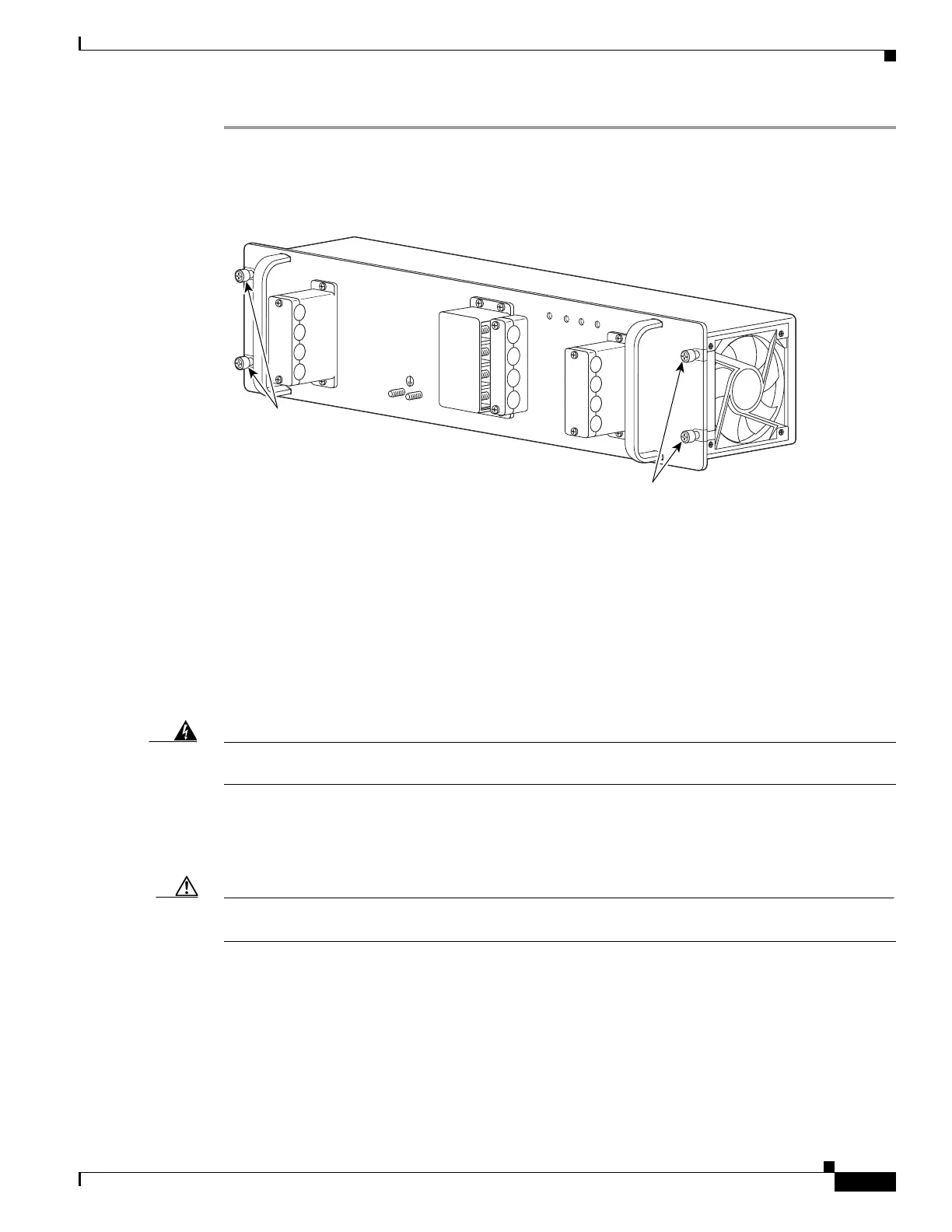
Figure 9-3 DC-Input Front Panel for 2700-W DC-Input Power Supply
Step 3
Remove the two screws securing each of the cable holder covers, and remove the cable holder covers off
the cable holders.
Step 4 Disconnect the DC-input wires from the terminal block.
Always disconnect the DC-input wires in this order:
• Positive (+)
• Negative (—)
• Ground
Warning
When installing the unit, the ground connection must always be made first and disconnected last.
Statement 42
Step 5 Remove the two tie-wraps from the ground cable. If there is a long cable tie securing the cable holders,
remove that as well.
Step 6 Loosen the captive installation screws on the power supply. (See Figure 9-3.)
Caution Use both hands to install and remove power supplies. Each PWR-2700-DC DC/4-input power supply
weighs 19.8 pounds (9.0 kg).
132218
Captive installation
screws
Captive installation
screws
PWR-2700-DC/4
-VE-1
-VE-1
-VE-2
-VE-2
IN
PU
T1
O
K
48V
-60V
=40A
INP
U
T2
O
K
48
V
-6
0V
=40
A
FA
N
O
K
OU
T
PU
T
FA
IL
ALL FASTENERS M
UST BE FULLY ENGAGED
PRIOR TO OPERATING THE POW
ER SUPPLY