9-17
Cisco SCE8000 GBE Installation and Configuration Guide
Chapter 9 Removal and Replacement Procedures
Installing a Module
Note If the captive installation screws are loose, the EMI gaskets on the installed modules will push adjacent
modules toward the open slot, reducing the opening size and making it difficult to install the replacement
module.
Step 5 Remove the module filler plate by removing the two Phillips pan-head screws from the filler plate. To
remove a module, follow the procedure in the “Removing a Module” section on page 9-20.
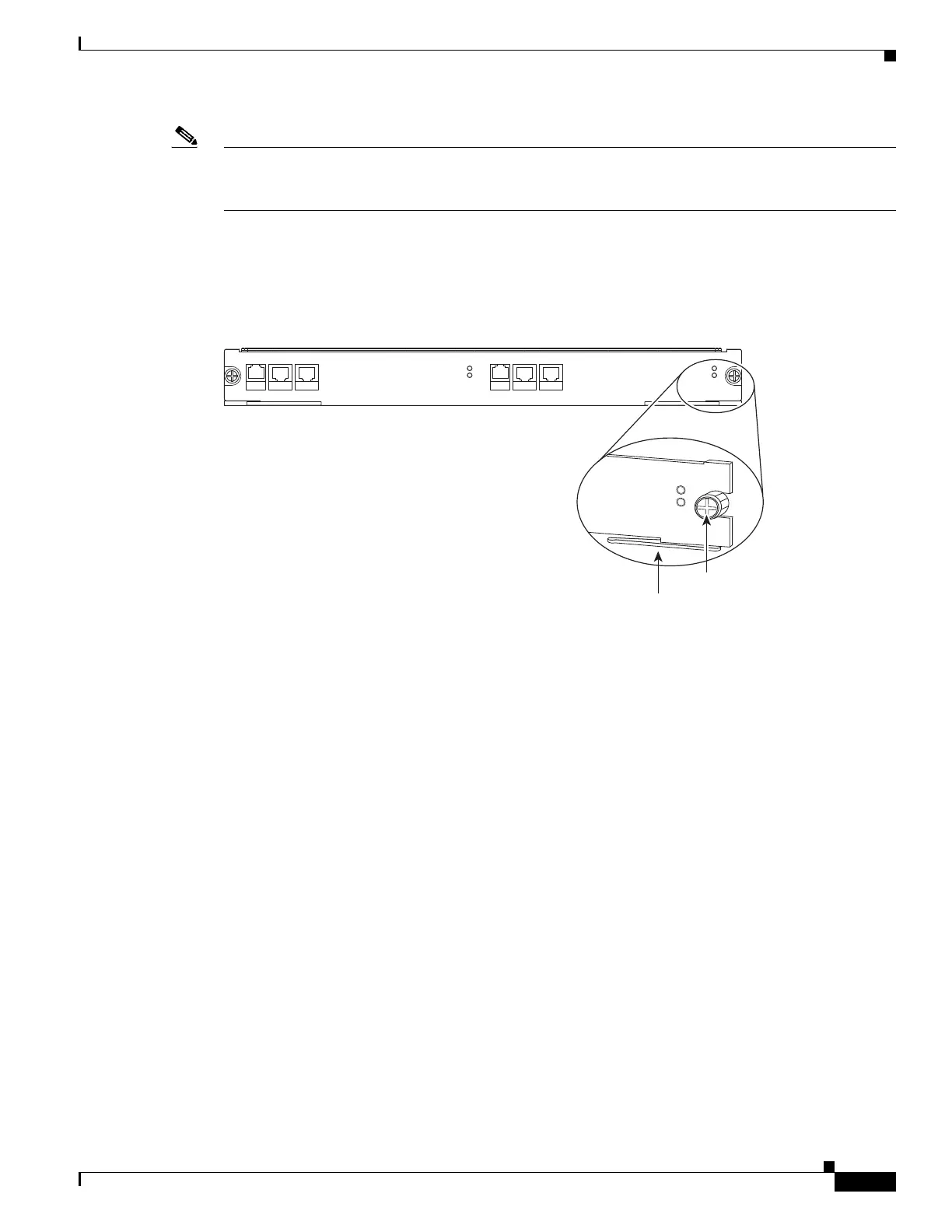
Step 6 Fully open both ejector levers on the new module. (See Figure 9-10.)
Figure 9-10 Ejector Levers and Captive Installation Screws
SCE8000 EXTENDED SERVICE CONTROL MODULE
SCE8000-SCM-E
STATUS
OPTICAL BYPASS
MASTER
SYSTEM POWER
10/100/
1000
LINK/
ACTIVE
OPTICAL
BYPASS1
CONSOLE PORT1
10/100/
1000
LINK/
ACTIVE
OPTICAL
BYPASS2
AUX PORT2
270901
Ejector lever
SCE8000 EXTE
N
DE
D SE
RVICE CONTRO
L MODULE
MA
S
TER
SYSTE
M
POWER
Captive
installation
screws