9-19
Cisco SCE8000 GBE Installation and Configuration Guide
Chapter 9 Removal and Replacement Procedures
Installing a Module
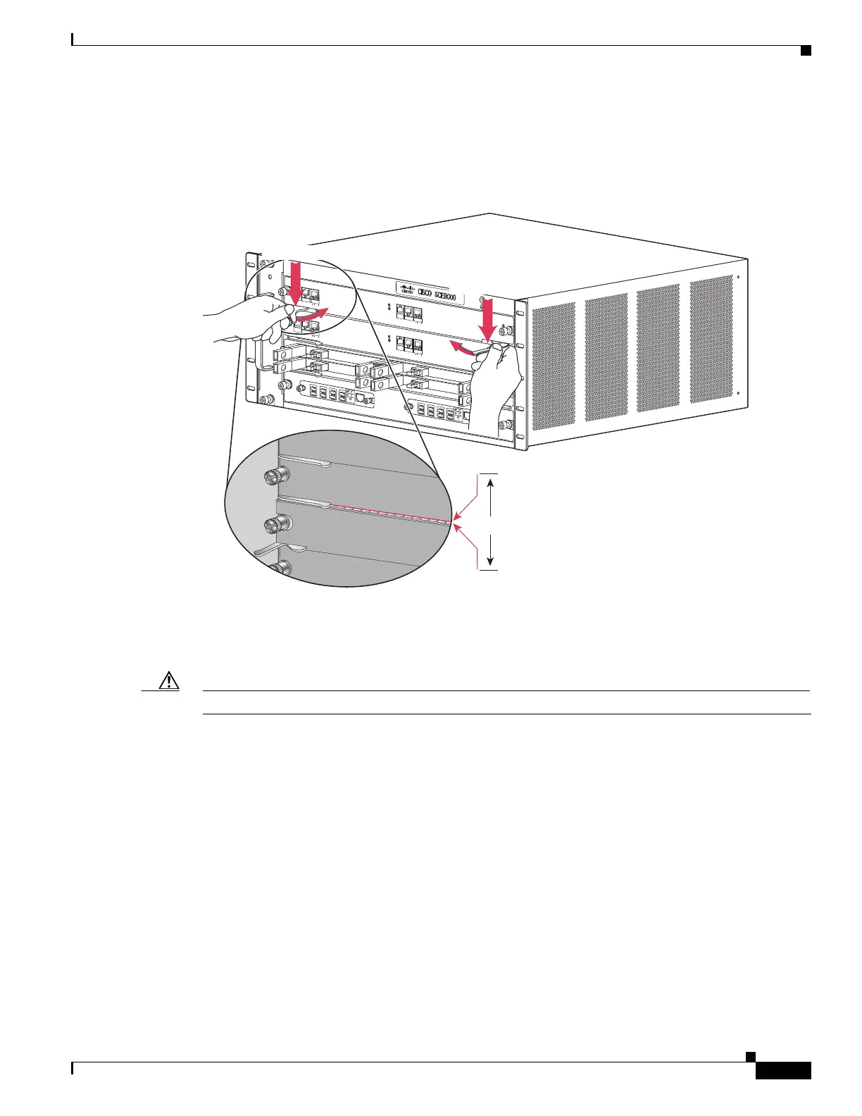
Step 8 Carefully slide the module into the slot until the EMI gasket along the top edge of the module makes
contact with the module in the slot above it and both ejector levers have closed to approximately 45
degrees in relation to the module faceplate. (See Figure 9-12.)
Figure 9-12 Clearing the EMI Gasket
Step 9 Using the thumb and forefinger of each hand, grasp the two ejector levers and press down to create a
small (0.040 inch [1 mm]) gap between the module EMI gasket and the module above it. (See
Figure 9-12.)
Caution Do not press down too forcefully on the ejector levers. They can bend and be damaged.
270908
FAN
S
TAT
U
S
S
CM
1
SC
M
2
S
IP
3
4
SCE
8000-FAN
SY
S
TE
M
P
O
WE
R
O
P
T
I
C
AL
B
Y
PA
S
S
S
T
ATU
S
AU
X
PORT
2
L
I
NK
A
C
T
I
V
E
M
A
ST
ER
S
C
E
8
000
E
X
T
E
N
D
E
D
S
E
RV
I
CE
CO
N
T
RO
L
MO
DU
L
E
OPTIC
A
L
B
Y
P
A
S
S
O
PT
ICA
L
BYP
A
SS
C
O
NSOLE
10 100
1
000
L
IN
K
A
CT
I
V
E
PO
R
T1
A
C
A
B
C
D
B
D
S
T
A
T
U
S
C
T
RL
OP
B-
S
C
E
8
K
-
M
M
O
PT
I
C
A
L
B
YP
A
S
S1
T
X
R
X
T
X
R
X
T
X
R
X
TX
R
X
A
C
A
B
C
D
B
D
S
T
AT
US
C
T
R
L
OPB-
S
CE
8
K
-
M
M
O
P
T
ICAL
B
Y
P
A
S
S
2
T
X
RX
T
X
R
X
T
X
R
X
T
X
RX
S
Y
S
T
E
M
P
O
WE
R
O
PT
I
C
AL
B
Y
PA
S
S
S
T
ATU
S
A
U
X
P
ORT 2
1
0
1
0
0
1
0
0
0
LI
NK
A
C
T
I
V
E
M
AS
T
ER
S
C
E
8
000
E
X
T
E
N
D
E
D
S
E
R
V
I
CE
C
O
N
T
RO
L
M
O
DU
L
E
S
C
E
80
0
0
-
S
C
M
-
E
S
C
E
8
0
0
0
-
S
C
M
-E
S
C
E
8
00
0-
S
IP
C
O
NSOLE
1
0 100
1
000
L
IN
K
A
CT
I
V
E
PO
R
T1
O
PT
ICA
L
B
Y
PA
SS
OPT
IC
A
L
B
YPASS
S
T
A
T
U
S
A
C
TI
VE/LINK
S
P
A
-1
X
1
0
G
E
-L-
V
2
S
T
AT
U
S
A
C
T
I
VE
/L
INK
S
P
A
-
1X
1
0
G
E
-
L
-
V
2
S
T
A
T
U
S
A
CT
I
VE
/L
IN
K
S
PA
-
1
X
1
0
GE
-
L
-
V
2
S
T
A
TU
S
A
CT
IVE/
L
I
NK
S
PA
-
1
X
1
0
GE
-
L
-
V
2
1
0
10
0
1
0
0
0
1mm
Gap between the module
EMI gasket and the
module above it.
Press down
Press down
 Loading...