To determine the number of power supplies needed for a given configuration, use the Cisco UCS Power
Calculator tool.
LEDs
One LED indicates power connection presence, power supply operation, and fault states. See Interpreting
LEDs, on page 14 for details.
Buttons
There are no buttons on a power supply.
Connectors
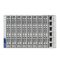
The AC power connections are at the rear of the chassis on the Power Entry Module (PEM) to support AC
input from the facility. The chassis has two PEMs (PEM 1 and PEM 2), and each supports 3 power supplies.
• PEM 1 supports PSUs 1, 2, and 3.
• PEM 2 supports PSUs 4, 5, and 6.
Each of the six hot-swappable power supplies is accessible from the front of the chassis. These power supplies
are Titanium efficiency, and they can be configured to support non-redundant, N+1 redundant, N+2 redundant,
and grid-redundant configurations.
Power Supply Configuration
When considering power supply configuration, you need to take several things into consideration:
• AC power supplies are all single phase and have a single input for connectivity to its respective PEM.
The customer power source (a rack PDU or equivalent) connects input power directly to the chassis
power entry module (PEM), not the actual AC power supplies.
• The number of power supplies required to power a chassis varies depending on the following factors:
• The total "Maximum Draw" required to power all the components configured within that
chassis—such as intelligent fabric modules (IFMs), fans, compute nodes (CPU and memory
configuration of the compute nodes).
• The Desired Power configuration for the chassis. The chassis supports non-redundant power supply
configuration, N+1 power supply configuration, N+2 power supply configuration, and grid power
supply configuration, which is also known as N+N redundancy.
• When connecting the chassis to facility power, make sure not to overload the capacity of a PDU or power
strip, for example, by connecting all PSUs to one PDU or power strip that is not capable of carrying the
total power draw of the chassis.
Cisco UCS X9508 Server Chassis Installation Guide
10
Overview
LEDs