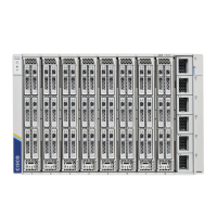
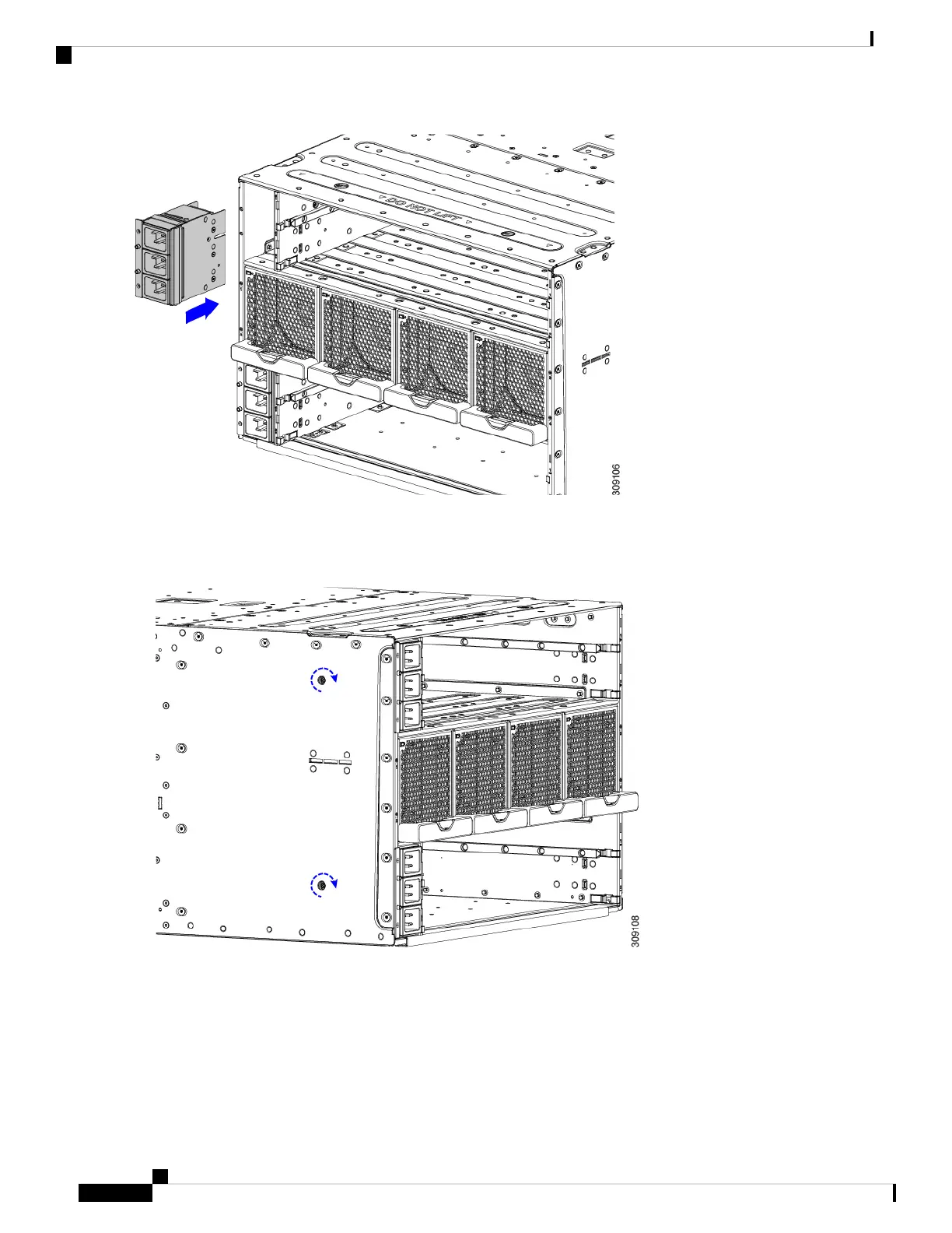
Step 3 Using a T10 screwdriver, tighten the captive screws which are easily identifiable because they are next to the electrical
ground icons on the chassis walls.
a) Tighten the exterior captive screws.
b) Tighten the interior captive screws.
Cisco UCS X9508 Server Chassis Installation Guide
80
Installing and Removing Components
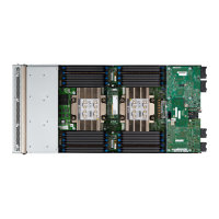
Installing the Power Entry Modules
 Loading...