3-5. Disassembly, Reassembly and Lubrication
3-21 CLP-621 & CLP-631
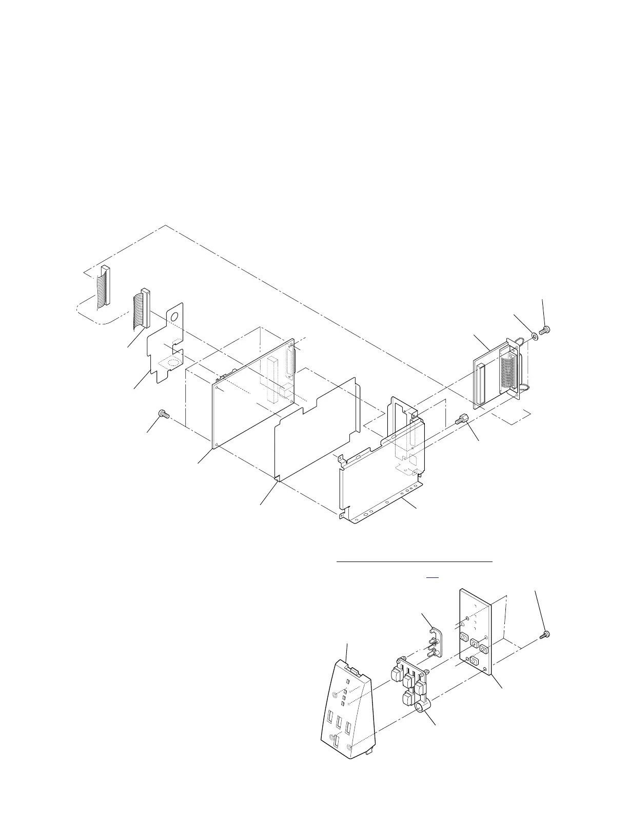
3-5-11. Main PCB Unit and Centro PCB Unit
1. Remove the Case U Unit. Refer to 3-5-2 “Case U”.
2. Remove the Main PCB Block. Refer to 3-5-10 “Main PCB Block, Power Supply Unit and
Control Panel Unit”.
3. Remove 2 screws (BHT (ST), M3x5) and 2 washers (EXT. T, 3 (NI)), and then detach the
Centro PCB Unit.
4. Disconnect the Centro Cable SA from the Centro PCB Unit and the Main PCB Unit.
5. Remove the Main PCB Sheet 2 from the Main PCB Unit.
6. Remove 2 lock screws and 4 screws (PHT (ST#3), M3x5), and detach the Main PCB Unit and
the Main PCB Sheet from the Main PCB Plate.
Plate, Main PCB
PHT (ST#3), M3x5
BHT (ST), M3x5
Lock Screw
SA, Centro Cable
Unit, Main PCB
Unit, Centro PCB
EXT. T, 3 (NI)
Sheet, Main PCB
Sheet 2, Main PCB
Note on reassembling:
• When the Main PCB Unit is replaced with new one,
perform the sensor adjustment. Refer to
3-6-1 “Transparent/Reflective Sensor Position Adjustment” on page 3-
40.
PHT (PT2T), M3x6
3-5-12. Ope-Pane PCB SA
LED, Window
1. Remove the Case U Unit. Refer to 3-5-2
“Case U”.
Cover, Ope-Pane
2. Remove the Control Panel Unit. Refer to
3-5-10 “Main PCB Block, Power Supply Unit
and Control Panel Unit”.
SA, Ope-Pane PCB
3. Remove 3 screws (PHT (PH2T), M3x6) and
detach the Ope-pane Cover.
4. Remove the Key Switch and the Window LED
from the Ope-pane PCB SA.
Switch, Key