© 1999-2017 Citrix Systems, Inc. All rights reserved. p.67https://docs.citrix.com
1. Disconnect the cable from the support 40G QSFP+/10G SFP+ transceiver. Replace the dust cap on the cable before
putting it away.
2. Unlock the support 40G QSFP+/10G SFP+ transceiver by moving the locking hinge to the UP position.
3. Hold the support 40G QSFP+/10G SFP+ transceiver between your thumb and index finger and slowly pull it out of the
port.
4. Replace the dust cap on the transceiver before putting it away.
5. Put the support 40G QSFP+/10G SFP+ into its original box or another appropriate container.
Warning
Do not look directly into fiber optic transceivers or cables. They emit laser beams that can damage your eyes.
Connecting the Cables
When the appliance is securely mounted on the rack, you are ready to connect the cables. Ethernet cables and the optional
console cable are connected first. Connect the power cable last.
Warning
Before installing or repairing the appliance, remove all jewelry and other metal objects that might come in contact with power
sources or wires. When you touch both a live power source or wire and ground, any metal objects can heat up rapidly and cause
burns, set clothing on fire, or fuse the metal object to an exposed terminal.
Connecting the Ethernet Cables
Ethernet cables connect your appliance to the network. The type of cable you need depends on the type of port used to
connect to the network. Use a category 5e or category 6 Ethernet cable with a standard RJ-45 connector on a
10/100/1000BASE-T port or 1G SFP copper transceiver. Use a fiber optic cable with an LC duplex connector with a 1G SFP
fiber transceiver, 10G SFP+, or 40G QSFP+ transceiver. The type of connector at the other end of the fiber optic cable
depends on the port of the device that you are connecting to.
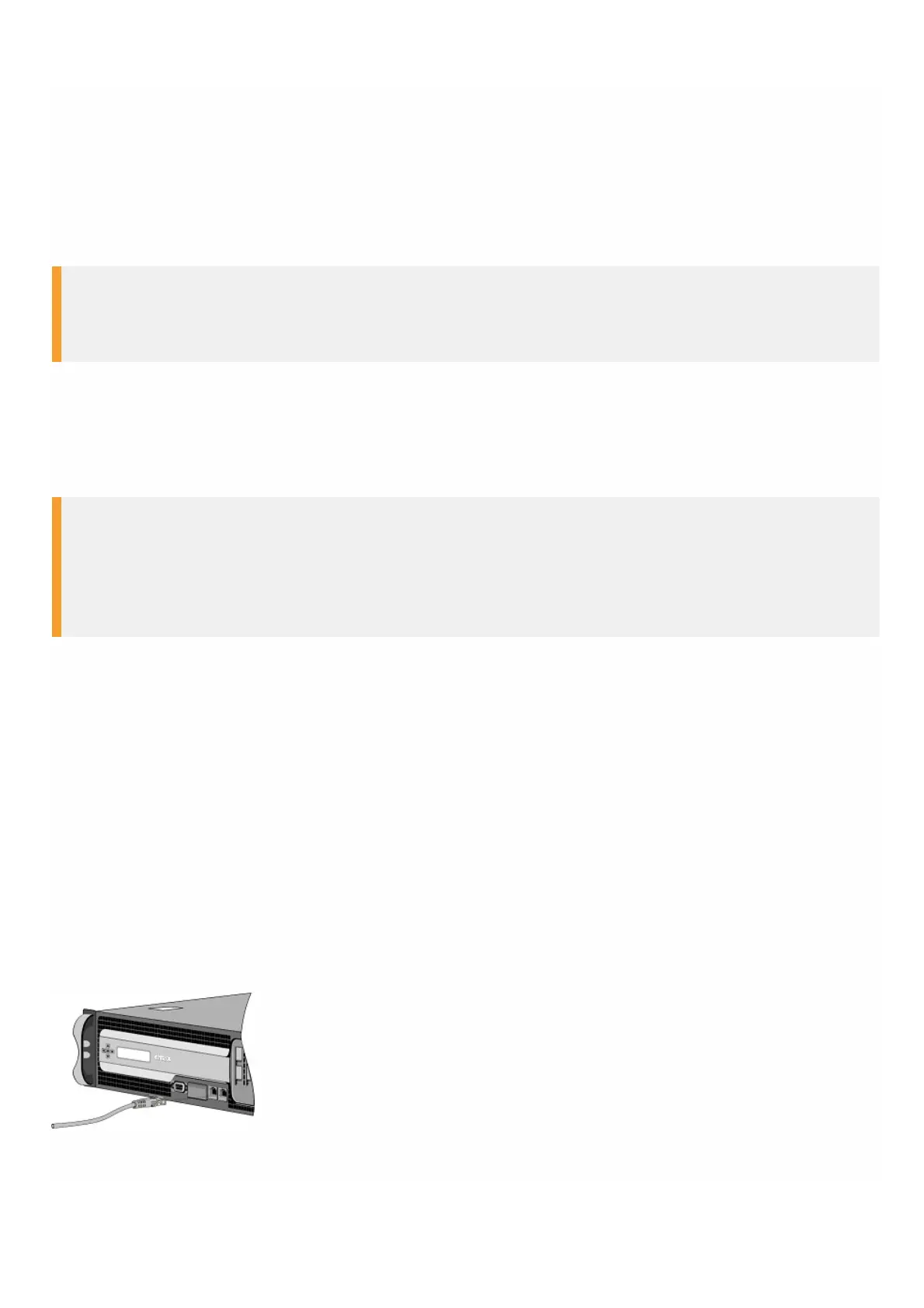
To connect an Ethernet cable to a 10/100/1000BASE-T port or 1G SFP copper transceiver
1. Insert the RJ-45 connector on one end of your Ethernet cable into an appropriate port on the front panel of the
appliance, as shown in the following figure.
Figure 7. Inserting an Ethernet cable
2. Insert the RJ-45 connector on the other end into the target device, such as a router or switch
3. Verify that the LED glows amber when the connection is established.