- 1 -
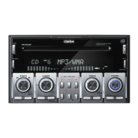
WXZ468RMP
Published by Service Dept.
Printed in Japan
Clarion Co., Ltd.
50 Kamitoda, Toda-shi, Saitama 335-8511 Japan
Service Dept.: 5-66 Azuma , Kitamoto-shi, Saitama 364-0007 Japan
Tel: +81-48-541-2335 / 2432 FAX: +81-48-541-2703
298-6340-00
Feb.2006
Service Manual
Model
This product is a lead free model.
Lead free solder is used in PWB stamped LF mark.
Please keep the following conditions when you repair.
1. Use lead free solder.
* Koki's lead free solder S3X-55M 0.6mm
(CLARION Parts No.642-0231-01)
* Koki's lead free solder S3X-55M 1.0mm
(CLARION Parts No.642-0231-02)
2. Use a nitrogen solder system.
3. Do not use "General solder" and "Lead free solder"
together.
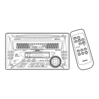
2-DIN 6-disc
CD/MP3/WMA Receiver
/ CeNET Control
(PE-2758E)
NOTES
* As for this model, CCC-TUNER is used.
When you exchange it due to the tuner pack (BL1:880-
2150A) trouble, it is necessary to adjust for S-meter etc.
Special JIG is necessary for an accurate adjustment.
The procedure document for the exclusive use jig is ap-
pended to it.
* Use only compact discs bearing the or mark.
* Some CDs recorded in CD-R/CD-RW mode may not be
usable.
* This product includes technology owned by Microsoft
Corporation and cannot be used or distributed without a
license from MSLGP.
* and logo are trademarks
or registered trademarks of Microsoft Corporation in the
United States and/or other countries.
* We cannot supply PWB with component parts in prin-
ciple. When a circuit on PWB has failure, please repair it
by component parts base. Parts which are not mentioned
in service manual are not supplied.
* Specifications and design are subject to change without
notice for further improvement.
SPECIFICATIONS
Radio section
Tuning system: PLL frequency synthesizer system
Receive range: FM 87.5MHz to 108MHz
(0.05MHz steps)
MW 531kHz to 1,602kHz
(9kHz steps)
LW 153kHz to 279kHz
(3kHz steps)
CD player section
System: Compact disc digital audio system
Usable discs: Compact disc
Frequency response: 10Hz to 20kHz(+/-1dB)
Signal to noise ratio: 90dB(1kHz)
Dynamic range: 90dB(1kHz)
Harmonic distortion: 0.01%
Channel separation: 75dB(1kHz)
MP3/WMA mode: MP3 ; Sampling rate 11.025kHz -
48kHz
Bit rate : 8kbps - 320kbps / VBR
WMA;Bit rate;48kbps-192kbps/VBR
Logical format(File system);
ISO9660 level 1, 2 or JOLIET or
Romeo
Audio amplifier section
Output power: 27W x 4ch (DIN 45324, +B=14.4V)
Continuous average power output:
17W x 4ch
(4 ohm, 20Hz to 20kHz, 1%THD)
Bass control action: +14dB, -12dB(60Hz/80Hz/120Hz)
Treble control action: +/-12dB(8kHz/12kHz)
9 Band-G-EQ: 1 oct step GAIN +/-12dB
(63Hz to 16kHz)
Line output level: 1.8V(CD 1kHz)
General
Power supply voltage: 14.4V DC
(10.8V to 15.6V allowable)
Ground: Negative
Current consumption: Less than 15A, 3A
Speaker impedance: 4 ohm(4 ohm to 8 ohm)
Dimensions(mm): 178(W) x 100(H) x 160(D)
Weight: 2.3kg