Clear-Com Communication Systems
ICS-102/62 Intercom Panel Instruction Manual
3-1
MAINTENANCE
INTRODUCTION
This chapter provides panel microprocessor resetting instructions,
troubleshooting guidelines, schematics, assembly drawings, and
component lists for the ICS-102/ICS-102T intercom panel.
The panel operates at 14 VAC, supplied from an external transformer.
Transformers can be ordered for either 117 VAC or 220 VAC.
PANEL RESET
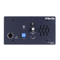
The panel’s microprocessor has a reset button located in an unmarked
hole just below the “Intercoms” knob on the left side of the unit’s front
panel. If the panel is acting erratically, try resetting it by doing one of
the following:
• Insert a small screwdriver or a stiff piece of wire (such as a bent
paper clip) into the hole and push the reset button.
• Unplug the panel from AC power and reconnect.
Troubleshooting
When experiencing the symptoms listed below, attempt the following
solutions in the order outlined. The solutions are listed in order of
difficulty with the first being the most simple and easy.
• The panel’s LEDs and push-button lights fail to light.
1. Check mains AC power into the panel.
2. Ensure the external power supply is properly connected to the
panel.
3. Replace the panel.
• The LED indicator above a selector key does not light when the
key is pressed.
1. Ensure the selector key has a label assigned to it (the LED indicator
will not light without an assigned label).
2. Reset the panel.
3. Replace the panel.
• The panel appears to activate talk paths, but other panels can’t
hear the panel operator.
1. Check “Mic On/Off” and “Panel Mic” buttons to ensure the intended
microphone is selected and on.
3