RADIUS SL 860 07.2019 en 58
11 List of illustrations
Page
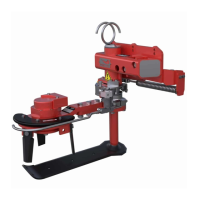
Figure 1 General view RADIUS SL 860 with grubber share ................................................................................... 6
Figure 2 Dimensions with share lengths, top view .................................................................................................. 7
Figure 3 Dimensions with disc coulter, side view .................................................................................................... 7
Figure 4 Attachment two-sided front ....................................................................................................................... 8
Figure 5 Support wheels for height guidance ......................................................................................................... 8
Figure 6 Position nameplate ................................................................................................................................... 9
Figure 7 Nameplate ................................................................................................................................................. 9
Figure 8 Return into the tank ................................................................................................................................. 10
Figure 9 Hose connections on the basic unit ........................................................................................................ 15
Figure 10 Hose installation RADIUS 2-sided ........................................................................................................ 15
Figure 11 Sensor rod not actuated ........................................................................................................................ 17
Figure 12 Sensor rod actuated .............................................................................................................................. 17
Figure 13 Tension spring for strong weeds ........................................................................................................... 18
Figure 14 Changing the blade share ..................................................................................................................... 18
Figure 15 RADIUS with oscillating disc colter ....................................................................................................... 18
Figure 16 Stop block on the basic unit .................................................................................................................. 19
Figure 17 Stop block ............................................................................................................................................. 19
Figure 18 Attachment point ................................................................................................................................... 20
Figure 19 Replacement of control valve seal ........................................................................................................ 23
Figure 20 Lubrication schedule ............................................................................................................................. 24
Figure 21 Tightening torque table ......................................................................................................................... 26
Figure 22 Spare parts Basic body ......................................................................................................................... 27
Figure 23 Spare parts Mounting kit ....................................................................................................................... 28
Figure 24 Spare parts Shaft unit ........................................................................................................................... 29
Figure 25 Spare parts Control valve ..................................................................................................................... 30
Figure 26 Spare parts Control unit ........................................................................................................................ 31
Figure 27 Spare parts Swivel cylinder ................................................................................................................... 32
Figure 28 Blade shares with sensor rods and accessories................................................................................... 33
Figure 29 Spare parts Disk plow ø 300 mm (11.8") .............................................................................................. 34
Figure 30 Spare parts Disk plow ø 350 mm (13.8") .............................................................................................. 35
Figure 31 Spare parts Swivelling disk colter ......................................................................................................... 36
Figure 32 Spare parts Clearing body LW-1 .......................................................................................................... 37
Figure 33 Spare parts Lateral angle adjustment ‘S’ mechanical .......................................................................... 38
Figure 34 Spare parts Hydraulic installation for Lateral angle adjustment ........................................................... 39
Figure 35 Spare parts Oil flow divider with return oil manifold 50/50 with hoses ................................................. 40
Figure 36 Spare parts Bridge hose 1-sided operation with 2-sided hydraulic equipment, disconnectable .......... 43
Figure 37 Spare parts Retrofit kit manometer ....................................................................................................... 43
Figure 38 Spare parts Override valve, electromagnetic, 1-sided, without pressure relief valve ........................... 44
Figure 39 Spare parts Override valve, electromagnetic, 2-sided, with pressure relief valve ................................ 46
Figure 40 Spare parts Constant flow divider adjustable 1-25 l (0.25-6.60 gal.) .................................................... 49
Figure 41 Spare parts Constant flow regulator 0-25 l (6.6 gal.) and 0-50 l (13.2 gal.) with Mounting kit ............. 50
Figure 42 Spare parts Mounting kit B-quantity disconnectable for flow divider 0-25 l and 0-50 l ......................... 51
Figure 43 Spare parts Quantity B disconnectable + merged return...................................................................... 52
Figure 44 Hosing variant basic device RADIUS: 1-sided mounting ...................................................................... 54
Figure 45 Hosing variant 2 pairs of RADIUS on high clearance tractor ................................................................ 56
 Loading...