Disassembly
Removing and Installing the Processor 2 - 19
2.Disassembly
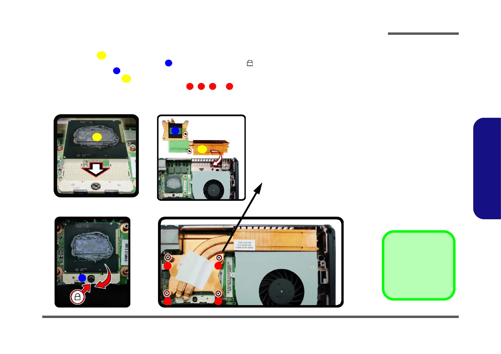
Processor Installation Procedure
1. Insert the CPU , pay careful attention to the pin alignment (Figure 15a), it will fit only one way (DO NOT
FORCE IT!), and turn the release latch towards the lock symbol (Figure 15b).
2. Remove the sticker (Figure 15c) from the heat sink unit.
3. Insert the heat sink unit
as indicated in Figure 15c.
4. Tighten the CPU heat sink screws in the order
, , & (the order as indicated on the label and Figure
15d).
5. Replace the CPU fan, component bay cover and tighten the screws (page 2 - 17).
c.
b. d.
B
a.
C
D
1
4
2
Note:
Tighten the screws in the order 1-2-
3-4 as indicated on the label.
3
A
Figure 15
Processor
Installation
a. Insert the CPU.
b. Turn the release latch to-
wards the lock symbol.
c. Remove the sticker from
the heat sink unit and in-
sert the heat sink.
d. Tighten the screws.
A. CPU
D. Heat Sink
•4 Screws