Page 31
SYSTEM DIAGRAMS
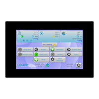
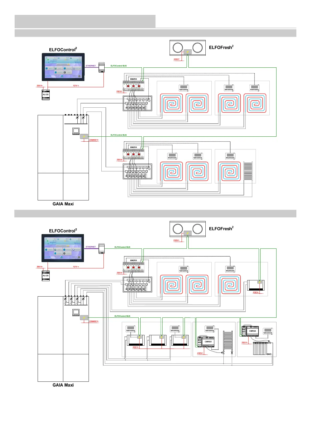
Indicative diagram
The components of the system are not indicated, because they must be specified by both the Designer and Installer (e.g. expansion tanks, vents,
cocks, calibration/safety valves, etc.)
SYSTEM TYPICAL DIAGRAMS: NEW BUILDING WITH RADIANT PANELS AND RADIATORS
SYSTEM TYPICAL DIAGRAMS: NEW BUILDING WITH RADIANT PANELS, FAN COILS AND RADIATORS
Ethernet/485
Converter
Ethernet/485
Converter