52
Electrical connections
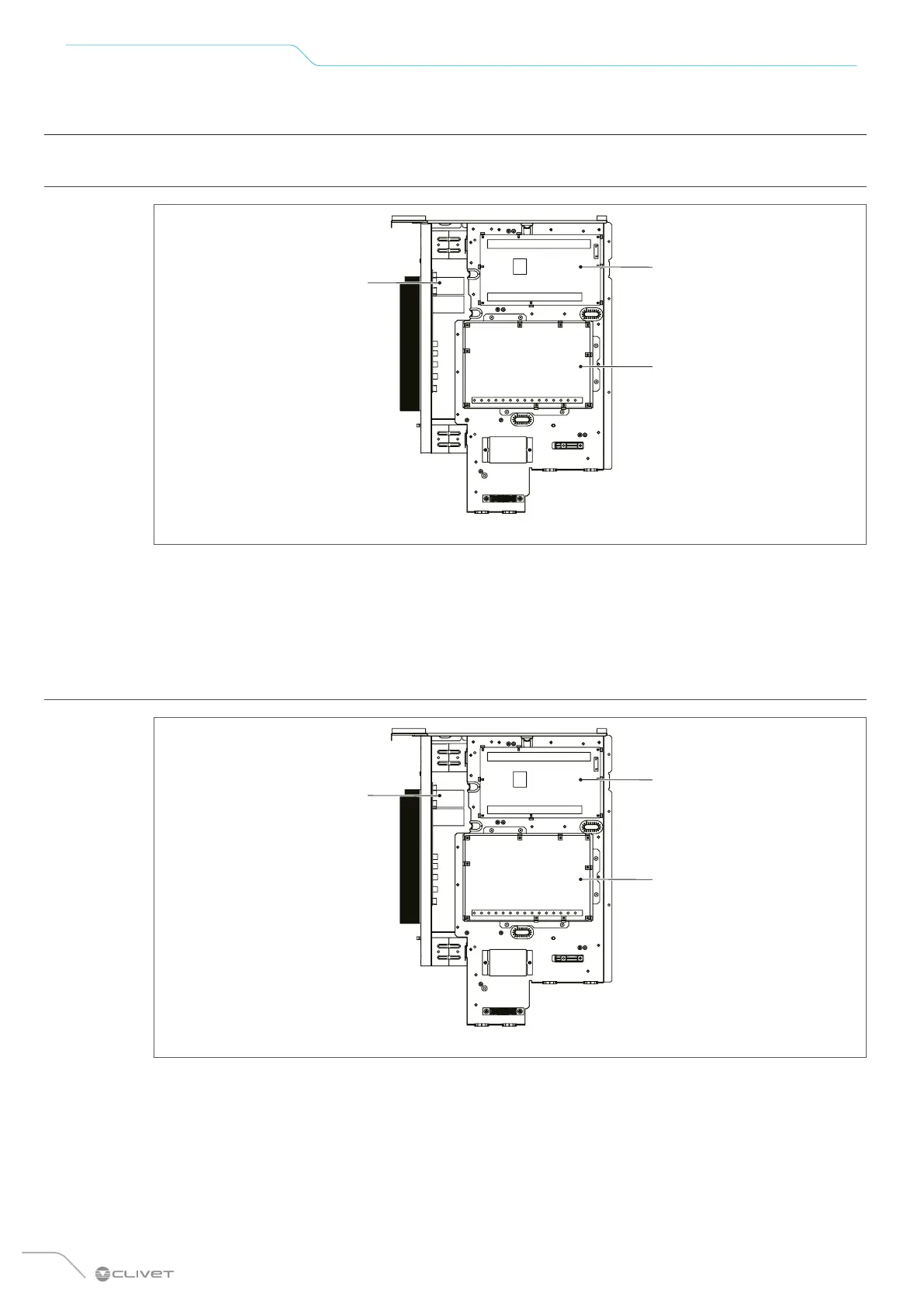
7.3 Control box
7.3.1 Sizes 2.1 to 8.1
Fig. 42
1 Inverter module (PCB A)
2 Main control board (PCB B)
3 Hydraulic module control board
The picture of the control box is for reference only.
7.3.2 Sizes 9.1 to 14.1
Fig. 43
1 Inverter module (PCB A)
2 Main control board (PCB B)
3 Hydraulic module control board
The picture of the control box is for reference only.
 Loading...