35
7 - CONTROL
ALARMS - TAB 3
code description description t.i. module input t.a.
ff110: Pre-low pressure cool Pre-alarm - low pressure COOL mode A
ff111: Pre-low pressure heat Pre-alarm - low pressure HEAT mode A
fF112: low pressure from AI Low pressure from analogic input AI 94U driver T1 X1 A/M
fF113: high pressure from DI High pressure from digital input DI 985 circuit 1 T3 X8 A/M
ff114: pre-high pressure Pre-alarm - high pressure A
fF115: high pressure from AI High pressure from analogic input AI 985 circuit 1 T2 X3 A/M
ff116: pre-max compr ratio
Pre-alarm max. compression ratio
(high pressure / low pressure)
A
fF117: min compr. Ratio
Min. compression ratio
(high pressure / low pressure)
A/M
FF119: max compr. Ratio
Alarm max. compression ratio
(high pressure / low pressure)
M
FF134: VaccumCirc Empty circuit AI 94U driver T1 X1 M
iI002: water pressure Low water pressure DI 687 central T5 DU1 A/M
iI006: flow switch utility side Flow switch utility side DI 687 central T3 X8 A/M
II007: freeze alarm Freeze alarm utility side M
ii008: pumps antifreeze alarm Utility side pumps On for antifreeze alarm A
II009:
inconsistent deltaT across
the exchanger
COOL:
Outlet temperature higher than inlet temperature
HEAT:
Inlet temperature higher than outlet temperature
A
iI120: flow on source side Flow switch source side DI 985 circuit 1 T2 X4 A/M
II121: freeze on source side Freeze alarm source side A
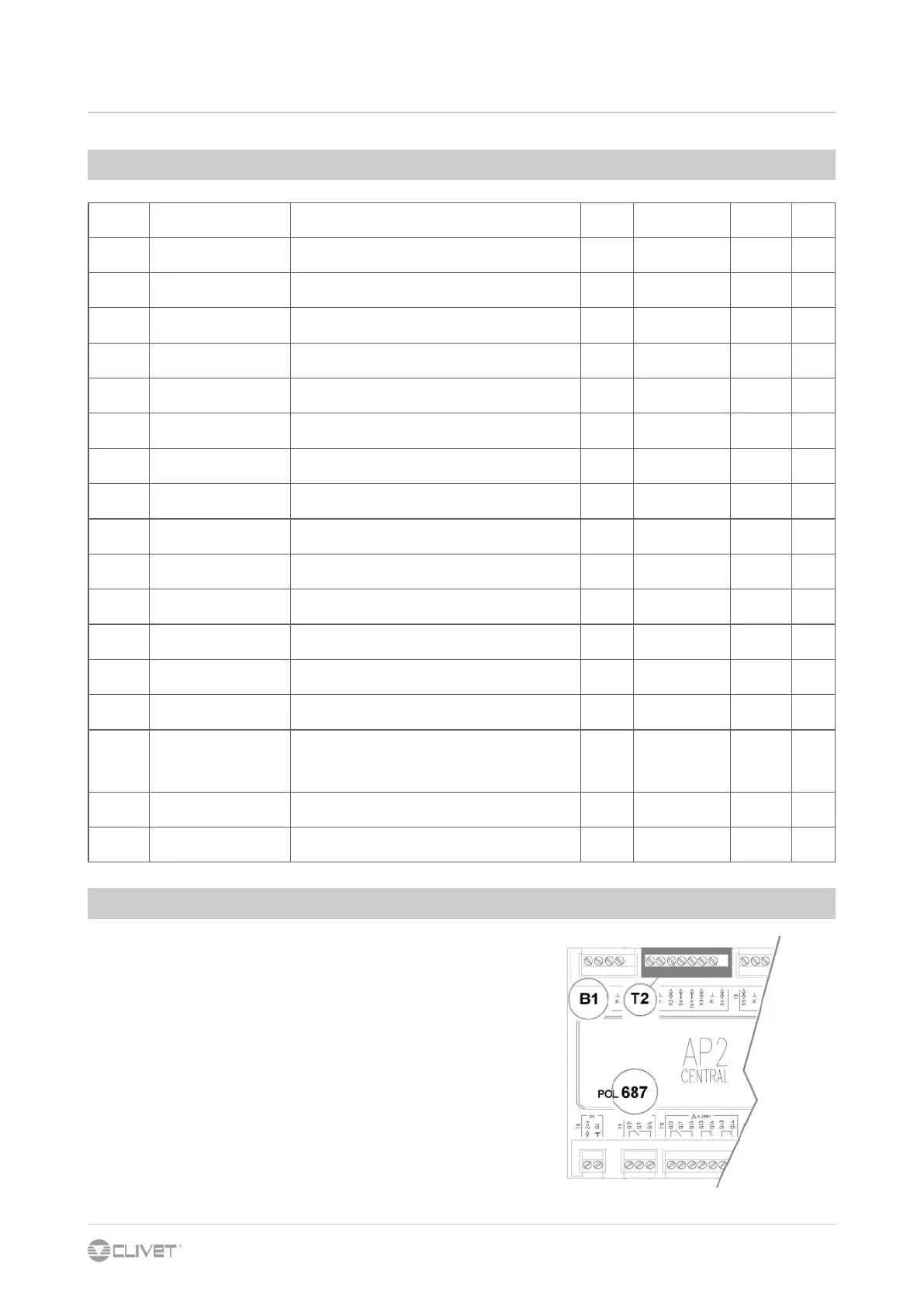
The stata code identifies the concerned circuit:
Es: S 1 100:CMP1 compressor1 starts = circuit 1
S 2 100:CMP1 compressor1 starts = circuit 2
The number of refrigerant circuits depends on series and size
of the unit.
Eg:
AI-687 T.IN H2OUtil_B1 Inlet water temperature
AI analogic input
687 main control module
B1 PIN
STATA
 Loading...