46-80 Installation and User Guide V1.0
17
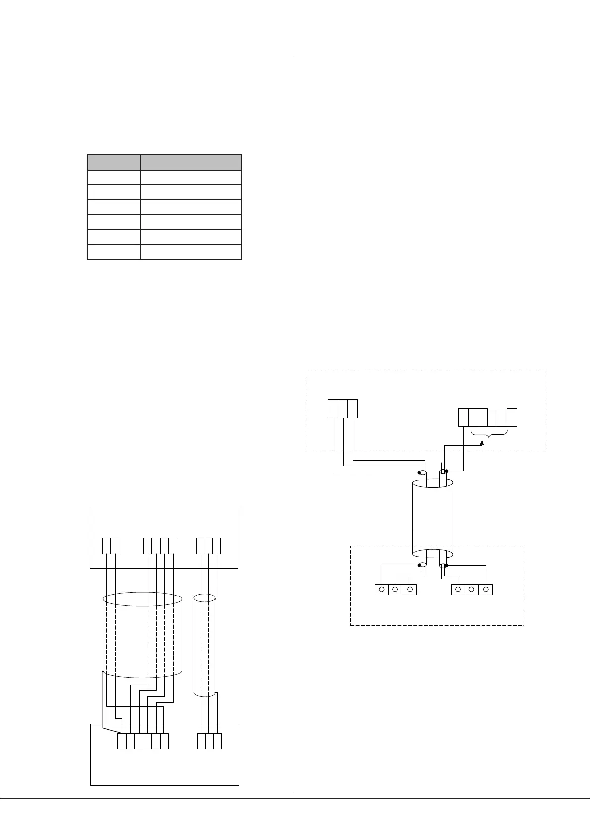
Connecting a PM4/4SA paging mic via the
analogue interface
Two connections are required: the paging mic audio signal
should be connected to the MICROPHONE 1/PAGE MIC
Input ([4] on page 13) and the control cable to the 6-pin
MIC 1 ACCESS port ([8] on page 13). The pinout of the port
is given below:
PIN FUNCTION
1 0 V
2 Zone 1
3 Zone 2
4 Zone 3
5 Zone 4
6 +Vsupply
Standard two-core screened audio cable may be used for
the audio signal, and stranded six-core cable with an overall
screen for the control cable. (Note that ‘-SA’ versions of PM
Series microphones cannot be powered by the 46-80, and
require an external PSU.)
Connections on the PM microphone are made via the rear
cable access glands and screw terminal blocks on the internal
PCB (TERM1, TERM4 and TERM8 in the example shown
below). Full connection details and notes on power supply
considerations can be found in the PM Series Installation and
User Guide.
The diagram below shows both cable connections between a
PM4 and a 46-80. Note that the DC power supply connection
will not be required if the PM microphone is powered
independently (either by a local PSU or via the network from
another PM unit).
TERM8TERM2TERM1
HOT COLDGNDZ1 Z2 Z3
Z4
0 V
+ V
MIC 1 INPAGING ACCESS
HOT COLDGNDZ1 Z2 Z3
Z4
0 V
+ V
PM4 PAGING MICROPHONE
46-80 MIXER
AMPLIFIER
Connecting a PM1 paging mic
The PM1 is a simple, passive paging microphone suitable for
situations where announcements are always made to the
same zone(s). It can be connected directly to the 46-80’s
analogue paging interface, the control cable being wired to
the pin(s) of the MIC 1 ACCESS port corresponding to the
zone(s) in which announcements are required. Any or all of
the zones may be paralleled if multiple zones need to operate
from the PM1.
Either a single 2-pair individually-screened cable may be
used (this gives the neatest nish), or two separate standard
microphone cables. Note that the PM1 does not require
DC power. Connections on the PM1 are made via the rear
cable gland in the base and the screw terminal blocks on
the internal PCB (U2 and U3). Full connection details can be
found in the PM1 Installation and User Guide.
The diagram below shows the connections between a PM1
and a 46-80. Use of 2-pair cable is assumed; the same wiring
principle is adopted if separate cables are being used for
audio and control.
U2 AUDIO
U3 ACCESS
GNDN/CN/O
HOT
COLD
SCN
MICROPHONE INPUT
MIC 1 ACCESS
CONNECT TO
ZONE(S) IN USE
46-80
PM1
Z1 Z2 +V
0 V
Z3
Z4
2 3
1
+
-
scn