46-80 Installation and User Guide V1.0
28
OPTIONS AND ADDITIONAL INFORMATION
RL-1 and RSL-6 Series remote control
plates – general considerations
Cloud RL-1 Series and RSL-6 Series remote control plates
are available in two form factors, to t single-gang UK or
American electrical back boxes. Back boxes of either the
recessed type or surface-mounting type may be used,
providing they are at least 25 mm deep.
The plates should be connected to the REMOTE MUSIC
CONTROL port of the relevant zone using single- or twin-
core screened cable as described on page 18. The plate
terminations are conventional screw terminals and the
remote MUSIC CONTROL port on the mixer is a 3-pin 5 mm-
pitch screw terminal connector.
The remote control plates are passive and thus do not draw
any current from the mixer.
Control of music source and level via
external DC
It may be necessary in some installations to adjust the music
level and select music source in one or more zones from an
external AV control system. If the REMOTE MUSIC CONTROL
ports are not required for RL-1/RSL-6 Series remote control
plates, they may be used to receive DC voltages from the
external system to effect these adjustments.
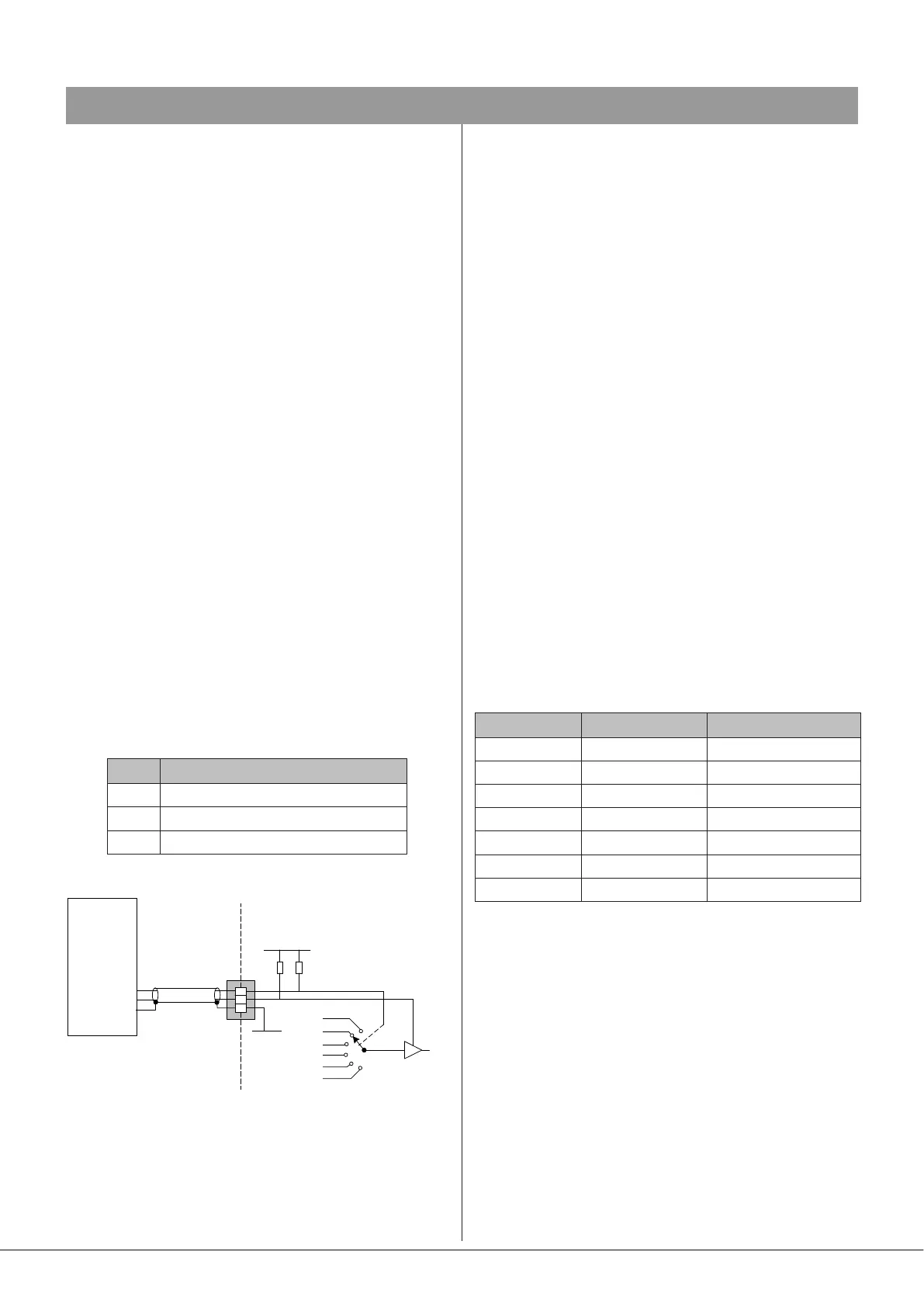
Both music source selection and level can be controlled over
their full ranges with a DC voltage of 0 to +10 V. The pinout
of the REMOTE MUSIC CONTROL port is as follows:
PIN USE
1 0 V ref.
2 Music level control (0 to +10 V)
3 Music source selection (0 to +10 V)
1
2
3
+12 V
0 V
4k7
15k
CONTROL
SYSTEM
0 V REF
LEVEL CONTROL
SOURCE CONTROL
MUSIC VCA
MUSIC SOURCE
SELECT
46-80
REMOTE
SOURCE+LEVEL
PORT
NOTE: If the control voltage source is not isolated from the
power earth, there is a small risk of creating a ‘ground loop’
by linking the mixer technical ground (0 V) to the ground
(0 V) of the equipment supplying the control voltages. To
minimise this risk, we suggest that all pieces of equipment be
in close proximity, and supplied from the same power outlet.
Music level
Music level in a zone may be varied over its full range by
applying a DC voltage of between 0 V and +10 V to pin 2,
the 0 V reference being connected to Pin 1. 0 V on pin 2
corresponds to maximum level and +10 V will produce
60 dB of attenuation. The rate of attenuation is approximately
165 mV/dB.
Note that there is an internal 4k7 “pull-up” resistor between
pin 2 and the internal +12 V rail. If pin 2 is left “oating”, this
pull-up will result in full attenuation. The output impedance
of the control voltage source should be low enough to
overcome the effect of this resistor.
Music source
Music source for a zone may be controlled by applying
various DC voltages of between 0 and +10 V to pin 3, the
0 V reference being connected to pin 1. 0 V at pin 3 will select
Line input 6 and between +6 V and +7.2 V will select Line
input 1. The other line inputs will be selected with intermediate
voltages. Taking pin 3 above +7.2 V will deselect all inputs,
making the zone effectively ‘off’ for music.
The table below lists the DC voltages required at pin 3 to
select each line input. The third column is the value of a
resistor which should be connected between pins 1 and 3 to
permanently ‘force’ a zone to a particular line input.
INPUT DC VOLTAGE RESISTOR VALUE
OFF >+7.2 V Open-circuit
Line 1 +6.0 V 16k
Line 2 +4.8 V 10k
Line 3 +3.6 V 6k8
Line 4 +2.4 V 3k9
Line 5 +1.2 V 1k8
Line 6 0 V short-circuit
Note that there is an internal 15k “pull-up” resistor between
pin 3 and the internal +12 V rail. If pin 3 is left “oating”, this
pull-up will cause ‘OFF’ to be selected. The output impedance
of the control voltage source should be low enough to
overcome the effect of this resistor.