46-80 Installation and User Guide V1.0
29
Using the Facility Port as an auxiliary
zone input
The Facility Port provides a balanced audio input to Zone 1. If
the port is not connected to an active remote module, it may
be used as a direct input to Zone 1 from other equipment
forming part of the system (for example, a permanently
installed DJ mixer which only ever needs to route its output
to Zone 1).
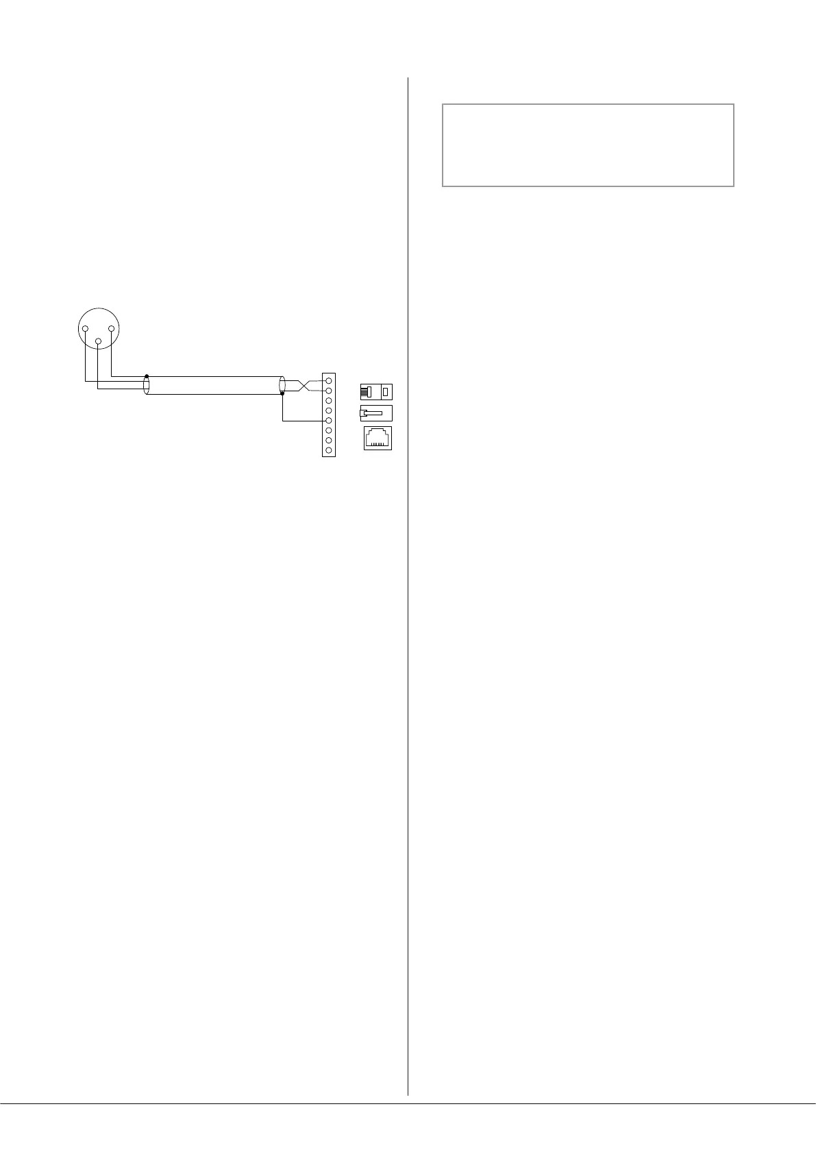
Wire an external balanced source to the facility port as
shown below:
1
8
7
6
5
4
3
2
ZONE 1 FACILITY PORT
(RJ45)
1
3
2
BALANCED
OUTPUT (e.g. XLR)
hot (+)
hot (+)
cold (-)
cold (-)
An unbalanced source may also be connected; the use of
balancing transformers is recommended.
Fitting CXL-80T transformers
NOTE: Full installation instructions are
included with the transformer.
The notes below are an abridged version.
The CXL-80T transformer allows Model 46-80 to be used
with 70/100 V-line loudspeaker systems. One transformer
will be needed for each Zone output to be congured for
70/100 V-line operation.
1. Disconnect the 46-80 from the mains and remove the
top cover.
2. With the rear panel facing you, t the transformers
to the right-hand chassis side using the M4 x 45 bolts
supplied. Four M4 holes are provided in the side panel
for this purpose.
3. Each transformer terminates in one 2-pin and one 3-pin
connector. The 2-pin one (black/red) is the input, the
3-pin one (blue/purple/white) is the output.
4. Identify the power amplier section feeding the Zone
Output to be converted: this is easily done by tracing
the blue/white twisted pairs back from the SPEAKER
OUTPUT connector. Unplug both ends of the twisted
pair and remove
5. Plug the 2-pin connector from the transformer into the
header on the power amplier board now vacated.
6. Plug the other connector from the transformer onto
the corresponding 3-pin header behind the SPEAKER
OUTPUT connector. There are two per Zone Output:
those nearer the rear panel are for 100 V-line operation,
the other set is for 70 V-line operation.
7. Enable the 65 Hz high-pass lters for the relevant
channels (J3, J4, J5 & J6). See page 30 for jumper
locations.
8. Replace the cover.
9. Do not re-power the 46-80 until the external speaker
connections have been made and the safety cover
retted over the SPEAKER OUTPUT connector.After
connecting the 70/100 V-line loudspeaker system (see
page 20), t the blanking plate from Step 2 onto the
hex spacers (Step 8) over the connector, with the printed
warnings outwards.