46-80 Installation and User Guide V1.0
30
APPENDIX
PCB jumper locations
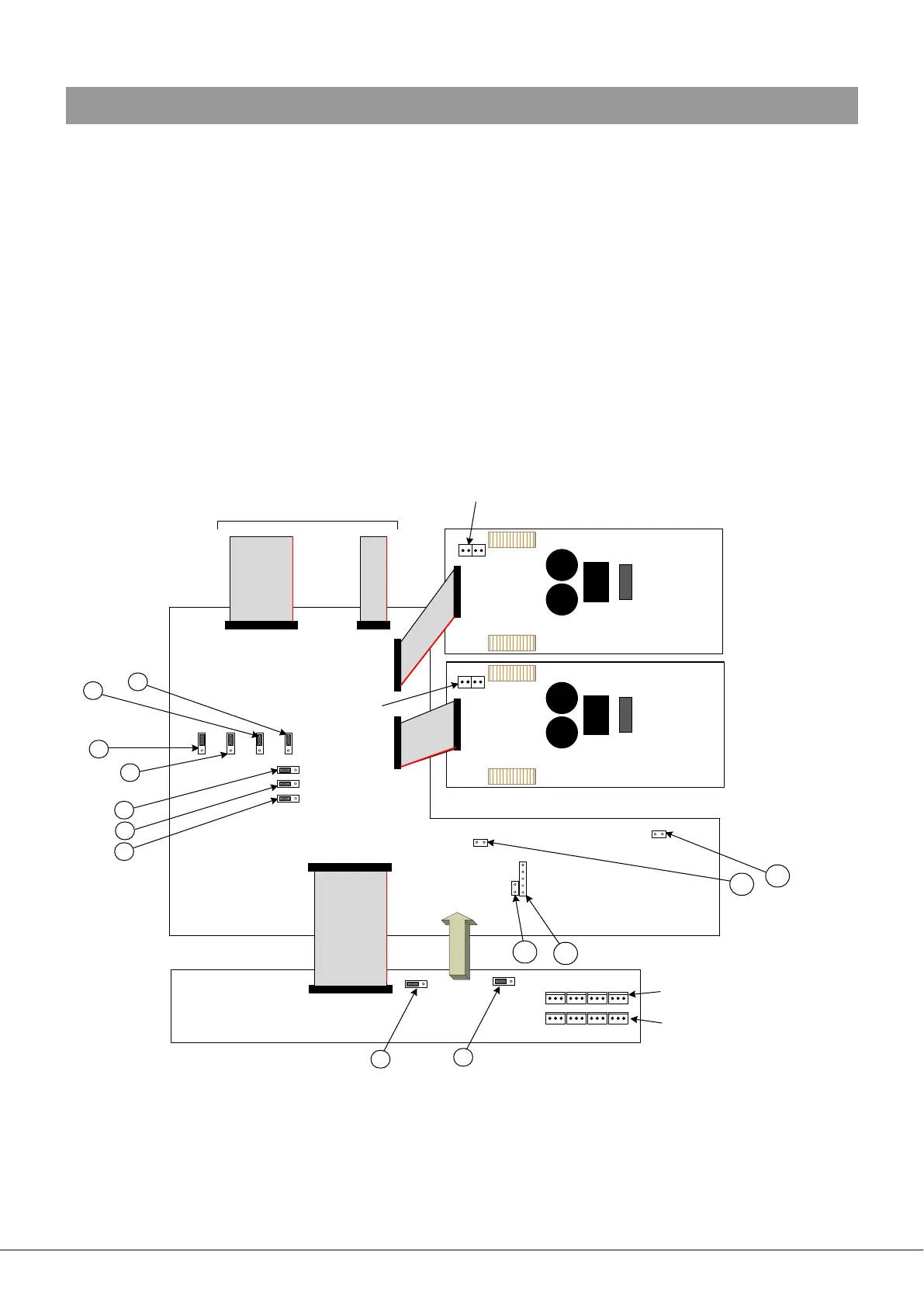
The 46-80 has various internal jumpers, the setting of which may require alteration during installation. The diagram below
shows the locations of the internal jumpers (not to scale) on the internal PCBs, and the table below lists each jumper and its
purpose, together with the factory default setting.
Note that the 46-80 has several PCBs. One of these, the upper PCB (mounted inside the rear panel) carries two jumpers (J1 and
J2), but all other jumpers are on the main PCB.
All “user” jumpers have two possible positions; the black square in the symbol on the diagram below indicates the default
setting. If any jumpers need to be changed, turn the 46-80 off and disconnect it from the mains. Undo the eight screws securing
the top cover of the unit and remove it. Use a pair of small pliers to gently remove the jumpers from the PCB headers and
reposition them as required. Ret the top cover using the same screws.
The PCB diagram (which is as viewed from the rear of the unit) also shows the locations of the headers relevant to retrotting
one or more CXL-80T transformers (see page 29).
MAIN PCB
POWER MODULE – Z1 & Z2
POWER MODULE – Z3 & Z4
UPPER PCB
TO FRONT PANEL PCB
Z1 Z2 Z3 Z4
Output connectors for
Lo-Z or 100 V-line operation
Output connectors for
70 V-line operation
J1
J2
J3
J4
J5
J6
J7
J8
J9
J10
J11
J12
J13
Power module output
headers – Z1 & Z2
Power module output
headers – Z3 & Z4
Z2 Z1
Z4 Z3