46-80 Installation and User Guide V1.0
21
If balancing transformers are not available, satisfactory
results are likely to be obtained by connecting pin 3 to the
signal pin of the unbalanced input (e.g., the tip of a phono/
RCA connector) and pin 1 to the connector’s outer screen. Do
not connect pin 2.
Note that all Zone 1 and 2 controls and settings on the front
and rear panels (levels, source selection, priority settings,
etc.) affect the auxiliary outputs.
Music Mute
External muting of music is available at the MUSIC MUTE
connector. Note that Music Muting only applies to Zone
Outputs 1 to 4 and the Auxiliary Outputs, and not to
the UTILITY/LOOP output. National or Local Authority
regulations governing such systems may require that normal
programme material (i.e., music) should be muted in an
emergency, to ensure that any emergency messages are
clearly audible.
The MUSIC MUTE input is on a 2-pin 5 mm-pitch screw-
terminal connector. It should be connected to the appropriate
alarm output on whichever building management system
registers the alarm (typically the Fire System). The alarm
output must be volt-free; if no such output is available, an
intermediate relay or other isolation device must be installed
between the alarm output and the Music Mute input.
Music Muting can be triggered by either normally-open
contacts, or normally-closed contacts. This selection is made
by rear panel DIP switch SW1/4 (MUTE – N/O OR N/C): the
default setting is N/O.
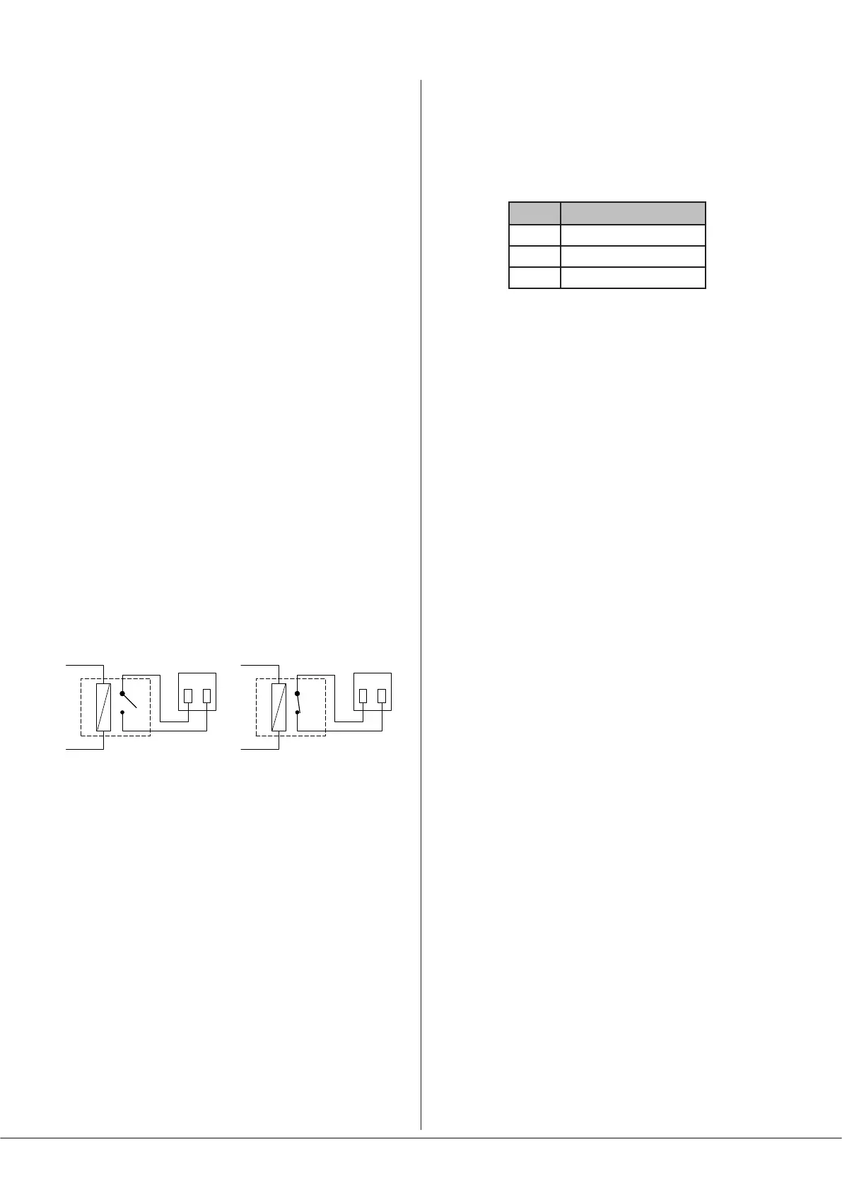
REMOTE MUSIC MUTE TERMINATIONS
1 2
MUSIC MUTE
INPUT
RELAY
NORMALLY OPEN (NO)
CONNECTION
1 2
MUSIC MUTE
INPUT
RELAY
NORMALLY CLOSED (NC)
CONNECTION
The red MUTE LED on the front panel ([9] on page 12)
illuminates when Music Muting is active
RS232 Serial Port
The 46-80 can accept commands from third-party AV
systems using standard RS232 protocol. A bidirectional serial
port - marked RS232 - is available on the rear panel ([18]
on page 13). This is a 3-pin, 3.5 mm-pitch screw-terminal
connector, and should be wired as below:
PIN CONNECTION
1 0 V
2 Data Rx
3 Data Tx
Note that not all control systems interpret “Tx” and “Rx” the
same way, and the installer should check whether pins 2 and
3 should be “crossed” within the cable.
See Page 26 for more details of RS232 control and an abridged
command set.