46-80 Installation and User Guide V1.0
16
Mono and stereo sources:
The mixing section of the 46-80 is mono; the stereo line inputs
are summed internally. Stereo sources should be connected
in a normal stereo conguration, using both L and R inputs. If
connecting a mono source with only a single output, it may
be connected to either the left or the right input.
Microphone inputs
Inputs MICROPHONE 1/PAGE MIC and MICROPHONE 2 are
intended for the direct connection of microphones. They are
electronically balanced and transformerless with an input
impedance of greater than 2 kohms and optimised for use
with microphones of 200 to 600 ohms impedance. The screw
terminal input connectors should be wired thus:
PIN CONNECTION
1 Screen
2 Signal ‘-‘ (cold)
3 Signal ‘+’ (hot)
Unbalanced microphones may be used by connecting pin 2
to pin 1 (cable screen) in the mating (male) screw-terminal
connector. 15 V phantom power is available, see page 22.
Either mic input may be routed to any of the zones in use,
at any level in each zone. Microphone priority may be set so
that any microphone announcements automatically reduce
the music level in that zone while the announcement is in
progress (see page 23 for more details.)
Paging system connections
Cloud PM Series paging microphones may be connected
directly to the 46-80. All models except the PM1 can use
either the Cloud Digital Paging Interface or an industry-
standard analogue interface; Model PM1 uses the analogue
interface.
PM microphones are available in 4, 8, 12 or 16-zone versions;
the PM-4 (or PM-4SA) is the appropriate model for use with
the four-zone 46-80.
Whichever connection method is employed, in order for
MICROPHONE 1/PAGE MIC 1 to function correctly with a
paging mic, rear panel DIP switch SW1/5 (PAGING MODE)
should be set to PG (switch down). For automatic music
ducking during an announcement, DIP switch SW1/3 (MIC
OVER MUSIC) should be set to ON (switch down). See page
23 for further information.
Connecting a PM4/4SA paging mic via the Cloud
Digital Paging Interface
The 46-80 is tted with a Cloud Digital Paging Interface; this
uses a RJ45 socket and is indicated as the DIGITAL PAGE MIC
connector on the rear panel ([9] at page 13). Cloud PM
Series Paging microphones may be connected directly with
Cat 5 cable; the single connection provides all audio, control
and power required by the microphone.
The port is able to supply 250 mA to power paging
microphones. This is adequate to power one or two PM-4
microphones. Cloud recommend that all ‘-SA’ models (with
spot announcement sound stores) are powered by a separate,
external PSU, as described in the PM Series Installation Guide.
(A suitable PSU is supplied as standard with all ‘-SA’ models.)
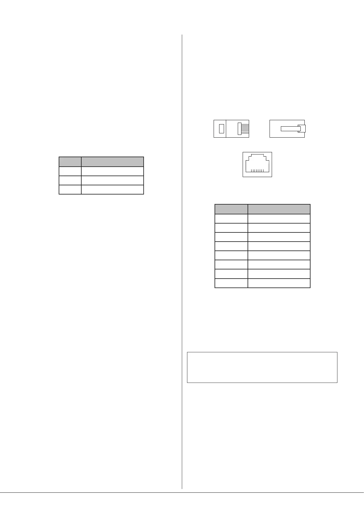
Connect the OUT socket of the PM Series microphone
to the DIGITAL PAGE MIC socket on the Zone Mixer with
Cat 5 cable. The standard Cat 5/RJ45 wiring convention is
shown below:
RJ45 PIN CAT5
1 Brown + White
2 White + Brown
3 Green + White
4 White + Blue
5 Blue + White
6 White + Green
7 Orange + White
8 White + Orange
The Cloud Digital Paging Interface allows multiple PM
Series microphones to be “daisy-chained”. If more than one
paging microphone is being installed – typically at different
locations in the building, connect the OUT socket of one to
the IN socket of the next.
IMPORTANT - Please refer to the PM Series Installation
Guide for full information regarding maximum cable
length, buss terminations and current requirements.
The earlier Cloud CDPM Series of paging microphones is also
compatible with the Digital Paging Interface.