46-80 Installation and User Guide V1.0
20
Speaker outputs (Lo-Z)
The power amplier outputs on Model 46-80 are available
on an 8-pin, 5 mm-pitch screw-terminal connector SPEAKER
OUTPUTS ([16] on page 13): rst remove the safety cover
protecting it (2 x M3 screws). Four mating 2-pin connectors
are supplied; the outputs for all four zones are present on the
connector. Connect to speakers using pairs of terminals as
shown in the table:
Pin (L to R) Panel
marking
Connect to:
1
Z1 -
Zone 1 output ‘-’
2
Z1 +
Zone 1 output ‘+’
3
Z2 -
Zone 2 output ‘-’
4
Z2 +
Zone 2 output ‘+’
5
Z3 -
Zone 3 output ‘-’
6
Z3 +
Zone 3 output ‘+’
7
Z4 -
Zone 4 output ‘-’
8
Z4 +
Zone 4 output ‘+’
Each output stage is designed to drive into an impedance
of not less than 4 ohms. Check the impedance of the
loudspeaker(s) in use and, taking into account any series and/
or parallel wiring, ensure that the total load on each channel
is not less than 4 ohms.
Speaker outputs (70/100 V-line operation)
Model 46-80T has four CXL-80T transformers pre-installed
and is thus ready for 70/100 V-line operation. Any or all zone
outputs of Model 46-80 may be converted for 70/100 V-line
operation by retrotting CXL-80T transformers as necessary.
See page 29 for details of CXL-80T transformer installation.
Note that immediately below the SPEAKER OUTPUTS
connector the rear panel is printed with check boxes marked
4 OHMS and 70/100V to indicate how the output is
congured for each zone. These will be marked according to
model type (46-80 or 46-80T) prior to shipment.
In Model 46-80T, the factory-tted CXL-80Ts are wired for 70
V-line operation in units for North American territories and
Australia, and for 100 V-line operation in units for Europe.
This can be changed if wished by moving internal connectors.
Use the same speaker wiring as shown for low-
impedance operation in the table above.
Ensure that the unit is disconnected from the AC
mains supply when making connections to avoid any risk of
electric shock
IMPORTANT - After making the connections and plugging
in the mating connectors, ret the safety cover over the
SPEAKER OUTPUTS socket. Making contacts carrying
70 V or 100 V inaccessible is likely to be a legal requirement
in most territories.
When the 46-80 is congured for 100/70 V-line operation,
the 65 Hz high-pass lters in each zone to be used in this
mode should be enabled: this is done by moving internal
jumpers. Model 46-80T has the lters pre-enabled at the
factory. See page 24 for full details.
Utility/Loop output
The UTILITY/LOOP OUTPUT is an additional balanced
line level output which is primarily intended for driving an
external hearing loop amplier, but can also can be used for
any other purpose. The source may be the programme in any
of the four Zones or always either Line Input 1 or Line Input
6, and is selected by rear panel DIP switches. See page 24
for full details.
The output connector is a 3-pin, 3.5 mm-pitch screw terminal
type ([17] on page 13), wired as follows
PIN CONNECTION
1 Screen
2 Signal ‘-‘ (cold)
3 Signal ‘+’ (hot)
Auxiliary line outputs
In large zones, it may be necessary to use additional ampliers
to obtain the necessary power to drive a greater number of
loudspeakers, or to drive some loudspeaker types requiring
higher power levels than the 80 W available from each of
the 46-80’s outputs. To permit the connection of further
ampliers - or any other equipment - balanced outputs from
Zones 1 and 2 pre-amplier sections are available at the rear
panel AUX OUT connectors, [14] at page 13.
The two connectors are of 3-pin, 3.5 mm-pitch screw terminal
type. Wire using the pinout in the table below:
PIN CONNECTION
1 Screen
2 Signal ‘-‘ (cold)
3 Signal ‘+’ (hot)
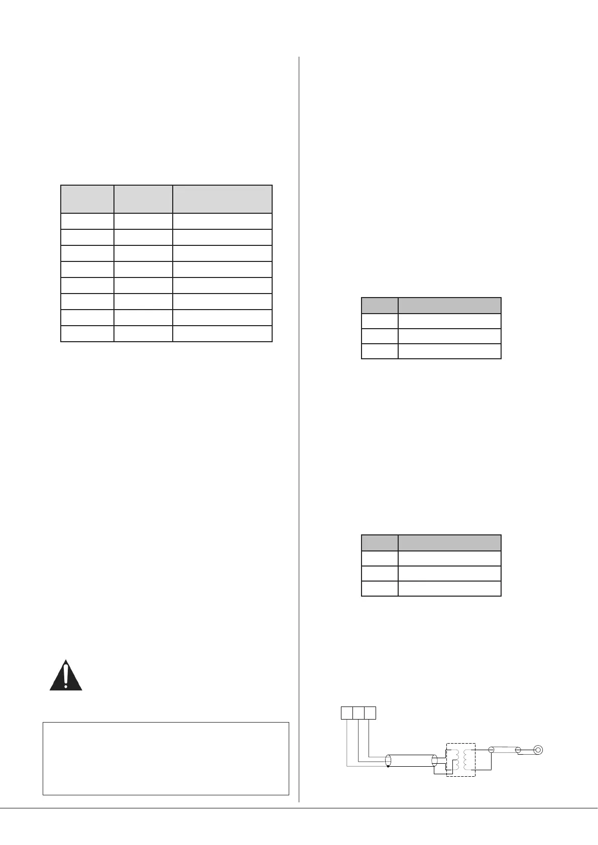
Connect to balanced inputs on external equipment with
twin-and-screen cable. The auxiliary outputs may also be
connected to unbalanced inputs: Cloud recommend the use
of external balancing transformers to achieve this, as shown
below:
AUX OUT:
pin 1 ground
pin 2 hot
pin 3 cold
+
-
SCN
Unbalanced
input
SCN
+
-
SCN
Audio balancing transformer
1 32