46-80 Installation and User Guide V1.0
24
High-pass lters
When an amplier is used to drive 70/100 V-line loudspeaker
systems, there is a risk of transformer saturation at high levels
and low frequencies. To prevent this, each of the 46-80’s four
channels is provided with a switchable 65 Hz high-pass lter.
This should be enabled for any channel being used to drive
70/100 V-line systems. On Model 46-80T, the lters will be
factory-enabled for all channels: on Model 46-80, they will
be disabled for all channels. If a Model 46-80 is to be used to
drive 70/100 V-line speaker systems, either by retrotting
one or more CXL-80T transformers, or by the use of external
transformers, they should be enabled.
The lters are enabled by moving internal PCB jumpers J3
(Zone 1), J4 (Zone 2), J5 (Zone 3) and J6 (Zone 4). See page
30 for locations of PCB jumpers.
Zone Routing (using output stages in
parallel)
In some installations, a higher power output may be required
in a zone than the 80 W the 46-80’s power stages are rated
at. To meet this requirement, the power stages may have
their inputs recongured so that two or more may be fed by
a single pre-amplier stage. For example, the power stages
for Zones 1 and 2 may be both fed by Zone 1’s preamplier
stage: in this case, the front panel Zone 1 controls will affect
both Zone Speaker Outputs, and the Zone 2 controls will
be non-operational. (Clearly, using this option reduces the
overall number of zone outputs available.)
The alternative Zone routings are selected by moving internal
PCB jumpers J7, J8 and J9 in various combinations. See page
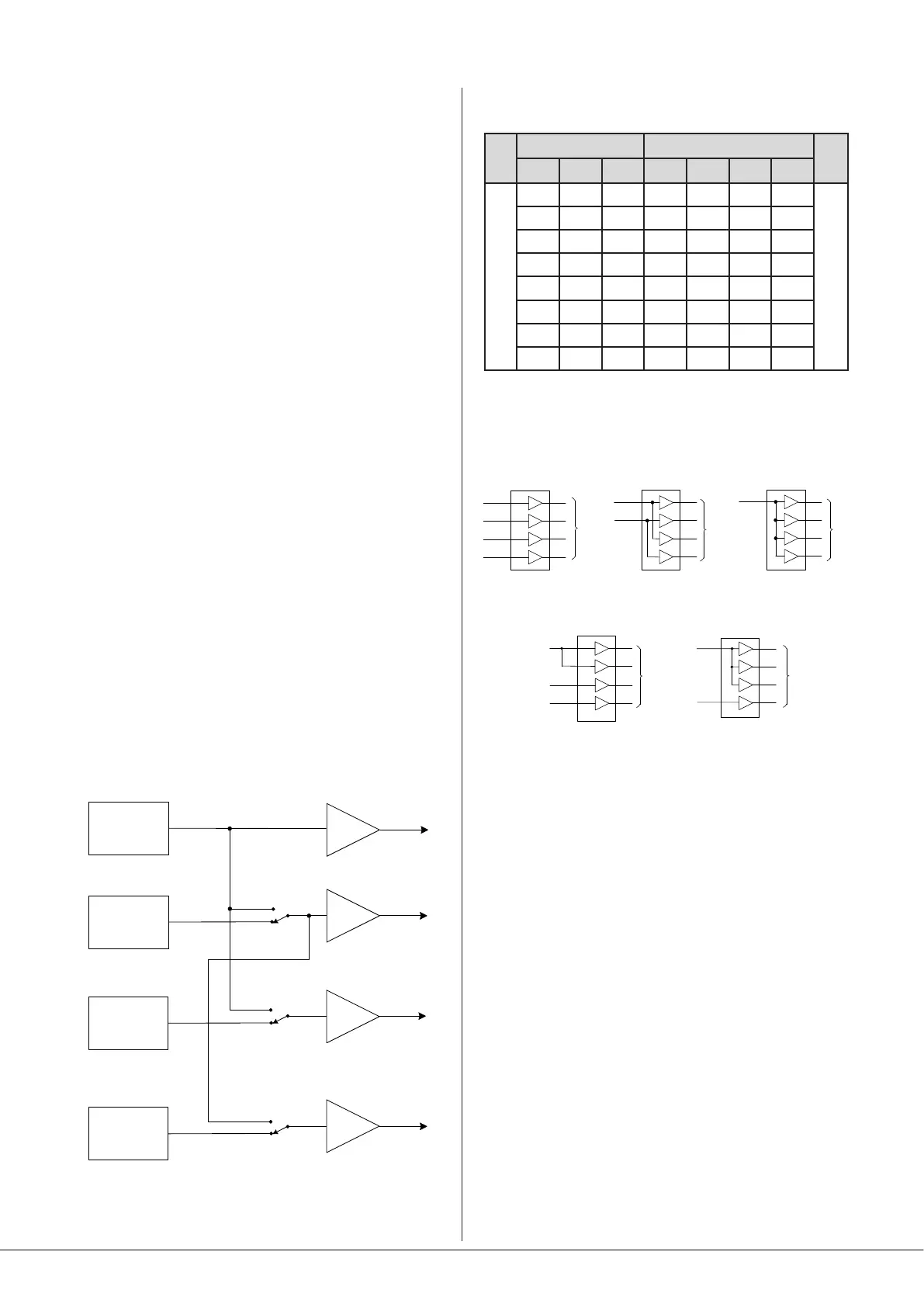
30 for locations of PCB jumpers. The diagram below
summarises the jumpers’ effects:
Z2
Zone 2 pre-amp
Z1
Zone 1 pre-amp
Z3
Zone 3 pre-amp
Z4
Zone 4 pre-amp
POWER
AMPLIFIER
STAGES
J7
DEFAULT
REROUTE
J8
DEFAULT
REROUTE
J9
DEFAULT
REROUTE
The table below shows all the routing congurations available
from the eight possible combinations of jumper settings:
JUMPER AMP CHANNEL
J7 J8 J9 CH1 CH2 CH3 CH4
R=REROUTED = DEFAULT
D D D Z1 Z2 Z3 Z4
INPUT ZONE
R D D Z1 Z1 Z3 Z4
D R D Z1 Z2 Z1 Z4
R R D Z1 Z1 Z1 Z4
D D R Z1 Z2 Z3 Z2
R D R Z1 Z1 Z3 Z1
D R R Z1 Z2 Z1 Z2
R R R Z1 Z1 Z1 Z1
The diagram below illustrates some useful congurations
with the necessary jumper settings:
IN 1
IN 2
IN 3
IN 4
4 X MONO CHANNELS
4 x MONO PARALLEL
TO POWER
STAGES
TO POWER
STAGES
TO POWER
STAGES
TO POWER
STAGES
TO POWER
STAGES
IN 1
2 x STEREO
IN 2
IN 1
IN 1
2 x MONO CHANNELS
+ 2 PARALLELED CHANNELS
IN 3
IN 4
1 x MONO
+ 3 x PARALLELED CHANNELS
IN 1
IN 4
J7 = D
J8 = D
J9 = D
J7 = R
J8 = R
J9 = R
J7 = D
J8 = R
J9 = R
J7 = R
J8 = R
J9 = D
J7 = R
J8 = D
J9 = D
Utility/Loop Output
The UTILITY/LOOP OUTPUT ([17] on page 13) is primarily
intended to drive an external hearing loop amplier, though
as a balanced line level output, it may be used for any purpose
required by the audio system.
Eight source options are available for the music component
of the signal at the Utility/Loop output, and is selected by
rear panel DIP switches SW3/6, SW3/7 and SW3/8 (UTILITY
SOURCE A, B and C respectively). The options are:
• The Utility/Loop output always follows the music source
selection made for any of the four Zones (either on the
front panel or via remote control). The MUSIC LEVEL
control for the selected Zone does not affect the level at
the Utility/Loop output. If Line 6 Priority is enabled for the
selected Zone, its effect will also be heard via the Utility/
Loop output, ensuring that e.g., emergency messages will
always be heard via the hearing loop. However, music will
not be ducked by Mic-over-Music priority, if it is enabled.
• The Utility/Loop output always follows the source
connected to LINE IN 1.