MAN.241 Rev.5 ENG - Use and maintenance manual S23 page 33 of 127
• lever 5 for tracks (*optional): it, upward, re-
stricts the tracks and downward enlarge
them.
Each lever, moved upward, runs the lifting of the sta-
bilizer and if moved downward the lowering of it.
In addition, there is an emergency red mushroom-
shaped button EB (Picture 13) that blocks the ma-
chine, removing the power supply to the control cir-
cuits. This button has priority over all other com-
mands; thus, it allows only manual descent to the
ground. The emergency button has a mechanical
locking device; therefore, it must be unlocked by turn-
ing it clockwise to reactivate the normal machine
working.
On the left side of emergency button, there is a
“dead man” stabilizers button SB (Picture 13): it
must be held pressed together with other levers to
stabilize or destabilize.
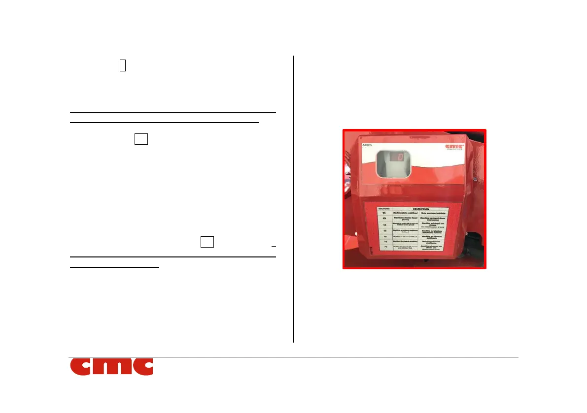
3.3.2 Display
The display (Picture 14), placed at the left side of the ma-
chine frame, shows the machine status or the error de-
tection codes when there is any anomaly or system
fault.
Picture 14: display.
Communicate the failure code shown on the
display, when you require technical assis-
tance to C.M.C. Service or authorized work-
shops.