SAILOR XTR GX-R2 system
98-175666-D Chapter 1: Introduction 1-9
1.1.3 Modem Unit (modem)
The GX Modem Unit comes in two different variants.
1. 407023A SAILOR GX Modem Unit with CX751 iDirect Core Module
2. 407523A SAILOR GX-R2 Modem Unit with SMB3315 iDirect Core Module
Both modems can be used with all SAILOR GX and SAILOR GX-R2 antenna systems.
The modem (GMU) comes in a 19” rack version. The modem has the following
interfaces and switch:
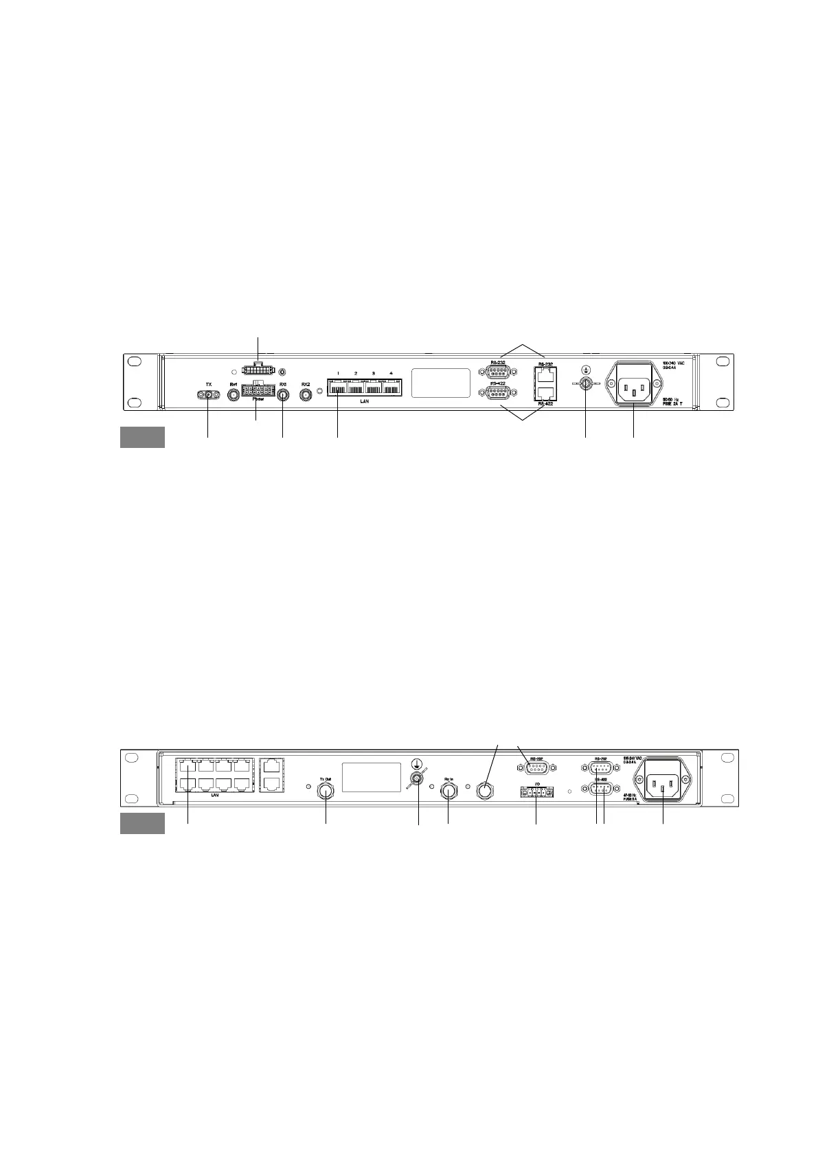
GMU (407523A)
• 4 x RJ-45 Ethernet (Modem control and user data).
• 2 x SMA connectors (50 Ohm) for Rx1 and Tx to BDU
(+ 2 x SMA not active, Rx2 and Ref).
• 2 x RS-422 interface for modem control (one DB9 and one RJ-45).
• 2 x RS-232 interfaces for modem control (one DB9 and one RJ-45).
• DC power in and out.
• AC Power connector.
• Ground stud with wing nut.
• On/Off power switch (at the front).
GMU (407023A)
• 8 + 2 ports, for modem control and user data.
• 2 x F connectors (75 Ohm) for Rx and Tx to BDU
(+ one not active).
• RS-422 interface for modem control.
• RS-232 interface for modem control
(+ one not active).
• I/O connector for Tx Mute and Rx Lock.
• AC Power connector.
Figure 1-9: GMU (407523A, connector panel)
Control via BDUTx Out Rx In GroundRS-422
RS-232
AC Power
GMU
DC power out
DC power in
Figure 1-10: GMU (407023A, connector panel)
Control via ACU Tx Out Rx InGround
Tx Mute &
Rx Lock
RS-422RS-232 AC Power
GMU
Not active

 Loading...


