Installation of the 7023A GX Modem Unit (CX-751)
98-175666-D Chapter 2: Installation 2-35
2.8 Installation of the 7023A GX Modem Unit (CX-751)
The following sections describe how to install and connect the 407023A modem to the
BDU.
2.8.1 Interfaces of the 407023A GX Modem Unit
Connector panel
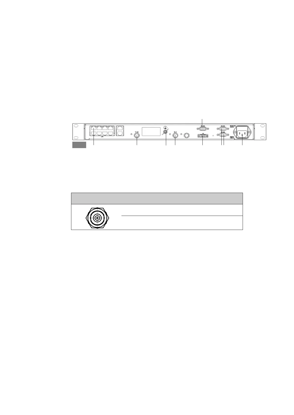
The following figure shows the connector panel of the modem.
Rx In and Tx Out connectors
The modem has an Rx In and a Tx Out connector. Use these connectors to connect the
BDU to the modem.
RS-232 and RS-422 connectors
The modem has one RS-232 and one RS-422 connector for control information to and
from the BDU.
Figure 2-32: Connector panel of the modem (407023A)
Control via BDU Tx Out Rx InGround
Tx Mute &
Rx Lock
RS-422RS-232 AC Power
GMU
Console port to modem
Outline(on BDU) Pin number Pin function
1 Inner conductor: 50 MHz clock, Rx/Tx
2 Outer conductor: GND (Shield)
Table 2-25: F connector, Rx and Tx, outline and pin assignment

 Loading...


