Installation of the 7523A GX-R2 Modem Unit (SMB3315)
98-175666-D Chapter 2: Installation 2-34
2.7.2 To install the 7523A modem
To install the modem, do as follows:
1. Slide the modem into a 1U space in a 19” rack, preferably directly below or above
the BDU.
2. Mount the screws in each side through the holes in the front and fasten the screws
to the rack. Make sure that the unit is mounted securely according to the
requirements for your 19” rack.
To ground the modem
Make sure that the grounding requirements are met. See the appendix Grounding and
RF protection for details about grounding.
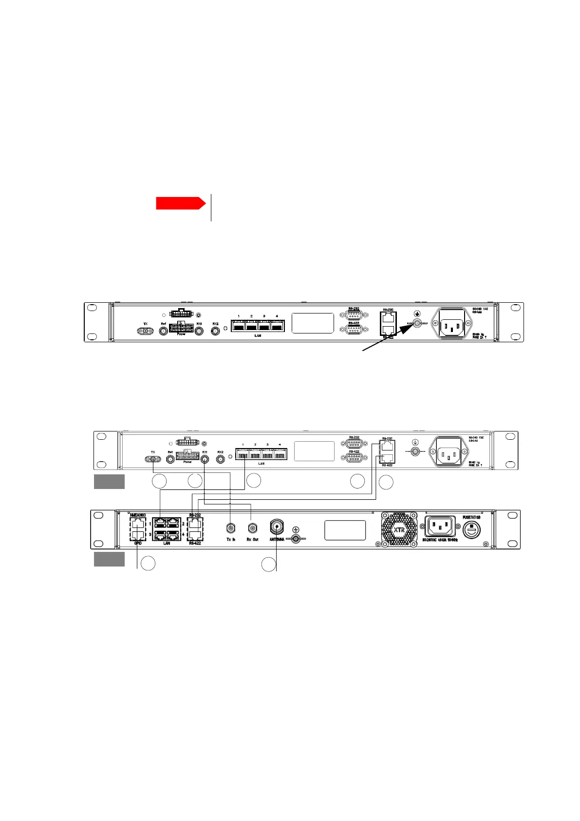
To connect the ADU, BDU and modem
The following sections show how to connect the ADU, BDU and the modem.
1. Connect the antenna cable to Antenna at the BDU and the antenna.
2. Connect Rx Out at the BDU to Rx In at the modem with the supplied cable
(coax, F-F, 1 m) and F-to-SMA adapter.
3. Connect Tx In at the BDU to Tx Out at the modem with the supplied cable
(coax, F-F, 1 m) and F-to-SMA adapter.
4. Connect RS-232 on the BDU to RS-232 at the modem.
5. Connect RS-422 on the BDU to RS-422 at the modem.
6. Connect LAN1 at the BDU to the upper left RJ45 connector at the modem.
7. Connect the green terminal block for the heading input from the gyro. For pin
allocation see NMEA 0183 RJ-45 connector on page 2-27.
Important
Make sure that the ventilation grills at the sides of the unit are not
blocked.
Figure 2-30: Ground stud, GMU (407523A)
Figure 2-31: Connection between ADU, BDU and modem (407523A)
1
2
3 4
5
AC power
AC power
GMU
BDU
7
6

 Loading...


